Solar Car Aeroshell
April 202611 min read
- CFD
- ANSYS Fluent
- Composites
- Siemens NX
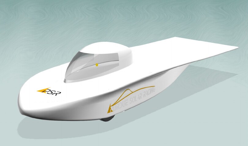
Three semesters on aero at Purdue Solar Racing, fall 2024 through fall 2025, the last two as team lead. We shaped our next car’s aeroshell, proved it in CFD, and built it in carbon fiber.
- Ran the shape trade study: modeled 3W and 4W catamaran concepts in Siemens NX and ran them in ANSYS Fluent.
- 30+ CFD runs with one locked setup, one variable at a time. Release geometry: 43.0 N drag at 20 m/s, 77.9 N net downforce.
- Built the real thing: CNC foam plugs, fiberglass negatives, then vacuum-infused tri-axial carbon. Finished shell weighed 20.25 kg, inside budget.
The trendy shape lost to the one we could build.
I joined Purdue Solar Racing in fall 2024 and led the aero team in spring 2025. Our mission was to shape the aeroshell for Artemis, our 2026 car, validate it in CFD, then build the real thing out of carbon fiber.
The Goal
We build for the American Solar Challenge, a multi-day, 1,500 to 2,000 mile endurance rally for student-built solar cars, run on public highways across the country. Every watt lost to drag is a watt the solar array has to earn back. The aeroshell, the car’s carbon fiber skin, sets most of that budget.
The aeroshell also has to close over a chassis, a driver, and 50+ structural components. Before any shape change counted, it was checked against the full car assembly in Siemens NX. Packaging kills more sleek ideas than the simulations do.
My share was the first 3W and 4W catamaran CAD, scaled from Nuna 12’s dimensions by 1.2, plus the CFD loop in ANSYS Fluent. On build days, I sanded, glassed, and infused alongside everyone else.
Picking a Shape
Three candidates made the shortlist: a 3 wheel catamaran (3WCAT) in the mold of Brunel Solar Team’s Nuna 11-12, a 4 wheel catamaran (4WCAT), and a 3 wheel bullet. Every subteam presented pros and cons, then ranked them. Stability screening came first. The bullet and the 4WCAT had to survive a 45 degree tilt test, while the 3WCAT got a gentler max-g bar from the on-track safety inspection.
I modeled both catamarans and put them through Fluent:
| Concept | Drag coefficient Cd | Drag |
|---|---|---|
| Asymmetric 4W catamaran | 0.234 | 47.8 N |
| Symmetric 3W catamaran | 0.253 | 61.7 N |
Early runs on scaled concept geometry. These two numbers only compare to each other. The tuned bullet numbers further down ran on the full-scale car.
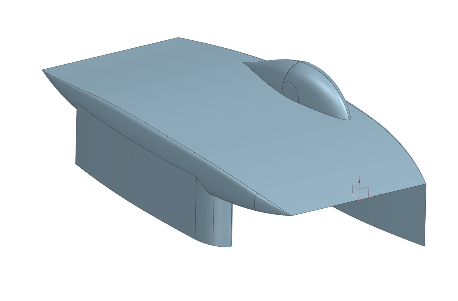
The bullet won anyway. Having built a bullet car the year before, we had a pile of actionable improvements ready to carry over. The bullet also had the easiest suspension packaging, simple center of gravity control, and symmetric wheel loads. The catamaran’s aero upside was real, but so were its unknowns. Unknowns eat build weeks. The 3WCAT’s strongest recorded pro boiled down to style points. Fair. Not enough to pick a shape on.
Sharpening the Bullet
Every simulation used the same recipe, which meant any drag delta traced back to the geometry change. These settings stayed fixed across all 30+ runs:
- Domain: 8 x 25 x 5 m box with a 3 x 22 x 2 m refinement zone.
- Mesh: 10 mm on the car, 1 mm at the wheel contact patches, inflation layers where the air does the most interesting things (nose, canopy, midsection, tail).
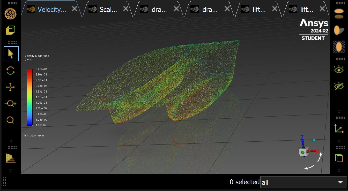
- Physics: steady state, SST k-omega, pressure-based, 20 m/s inlet.
- Convergence: 1e-4 on continuity, turbulence, velocities, and forces.
None of this was quick. A single run ate about eight hours, so my computer pulled night shifts. I queued a simulation before bed, slept on it, then squinted at the residuals over breakfast hoping everything had converged. That ritual ran through every iteration, one variable at a time:
| Run | What changed | Drag at 20 m/s |
|---|---|---|
2-6-25_base | top shell raised 1”, flatter bottom, canopy moved back | 27.1 N |
2-6-25_i1 | nose stretched to 50” | 27.5 N |
2-6-25_i3 | nose height squashed to 14” | 29.2 N |
2-6-25_i4 | nose height at 18” | 27.8 N |
aeroshell_v11 to v44 | real packaging folded in, canopy modeled from v38 on | 28.7 to 32.8 N |
The deltas look tiny. Two newtons at 20 m/s is 40 W the array has to earn back, for the whole race. Each change was a bet on the two ways a car makes drag. Pressure drag comes from shoving air out of the way. Skin friction comes from air rubbing along the body.
- Stretching the nose to 50” softened the pressure pile-up at the tip, but the longer nose added surface for the air to rub against. Friction gave back what pressure saved. Net +0.3 N, a wash.
- Squashing the nose to 14” promised a smaller face to the wind. The air disagreed with the tighter curve. Drag jumped 2.1 N, the worst of the set, because air does not care what looks good.
Across 30+ runs, no single change was the culprit or the fix. Progress came from small trades between pressure and friction, while packaging always collected its tax.
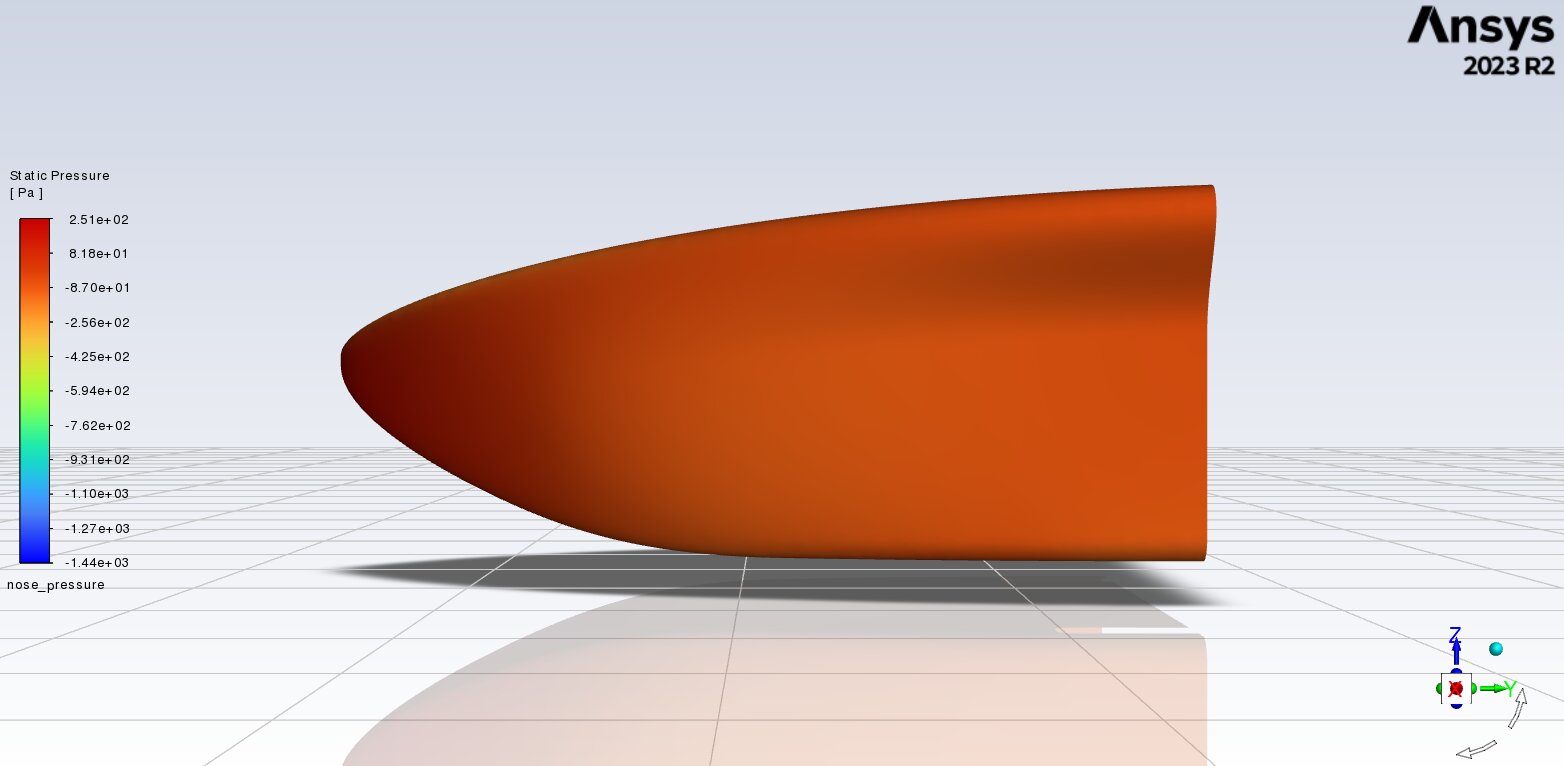
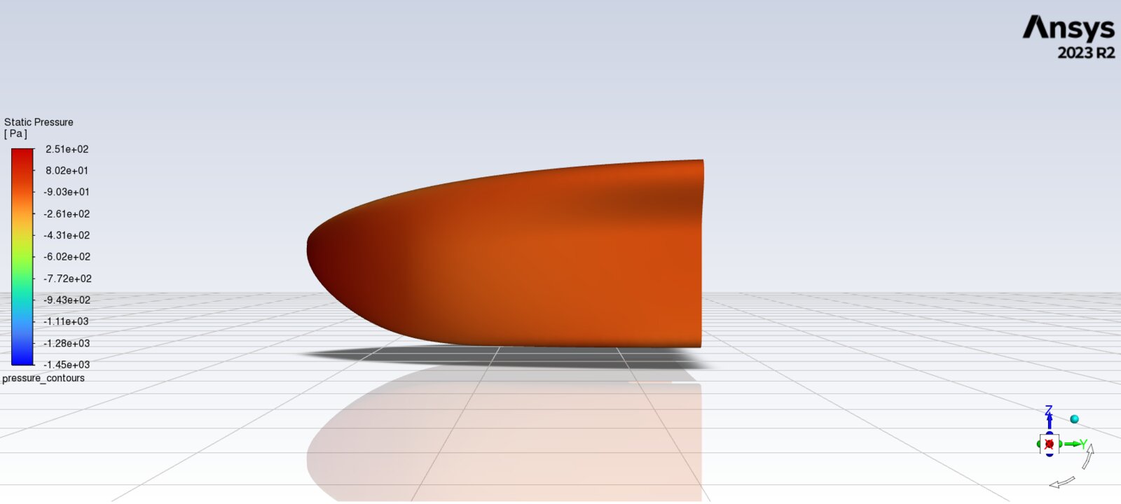
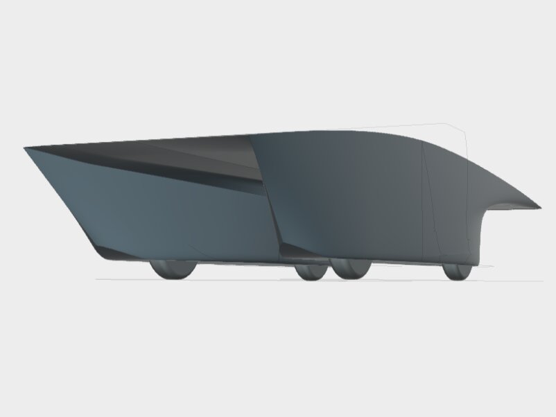
Where the release geometry landed at design review:
- 43.0 N of drag at 20 m/s, split 23.8 N pressure and 19.2 N skin friction.
- 77.9 N of net downforce. The shell does not try to fly.
- 20.25 kg finished shell, inside the 16 to 23 kg system budget.
- 227” x 66.5” x 47” bounding box.
Higher than the tidy nose-study numbers, and rightly so. This iteration models the whole car with every zone broken out, wheel covers and fairings included.
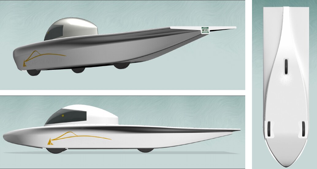 Side and top views of the release geometry.
The shell also grew a supporting cast. Each wheel hides under a sandwich cover, two skins of 200 gsm carbon prepreg over a 0.5” foam core, bolted together with 1” of breathing room around the tire. Spring-loaded fairings swing with the suspension and snap back to center.
Building It
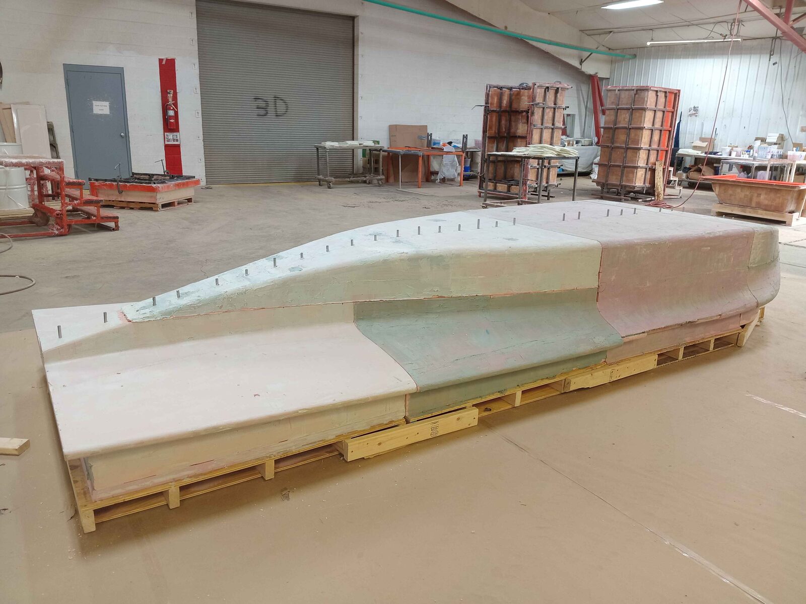
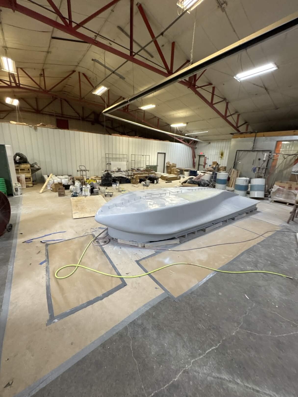
Two main sections make up the build. The plug is a full-size foam model of each shell. Off it comes the negative, the fiberglass mold, two pieces for the bottom shell and one for the top shell plus canopy. Inside that negative, the real part forms from tri-axial carbon locked in vinyl ester under vacuum. One build log covers both shells:
- Stack and glue pink insulation foam into blocks, then CNC each plug section.
- Assemble the sections, skim with bondo, and sand through
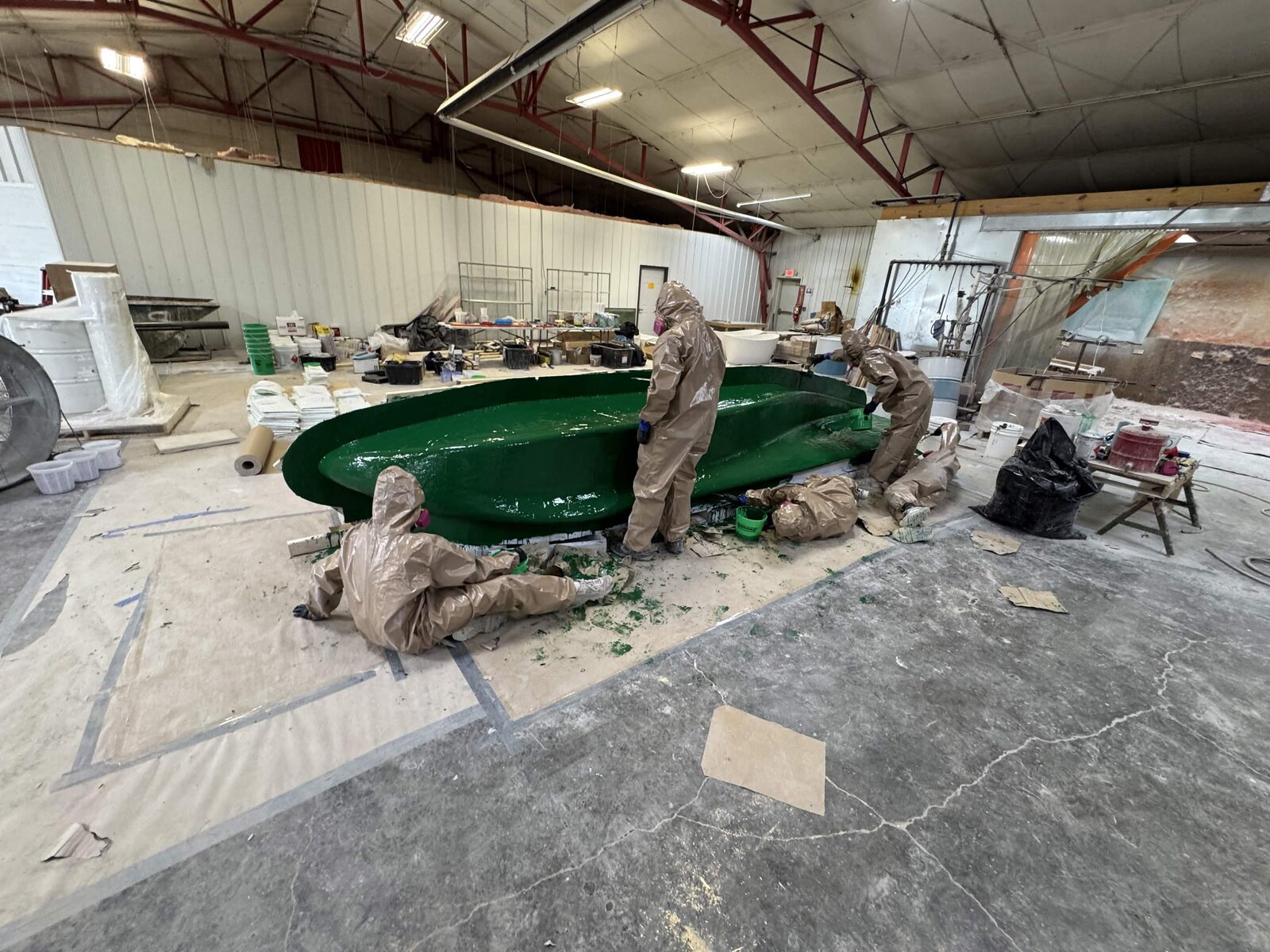
32 → 60 → 120 → 220 → 300 → 400 → 800 → 1500grit. - Prime, gel coat, and lay up the fiberglass negatives, 3 or 4 plies over a balsa core, braced with a 2x4 eggcrate so the mold holds its shape.
- Lay dry carbon in the negatives, bag it, pull vacuum, infuse.
- Demold, bond in the internal structures, epoxy to the chassis.
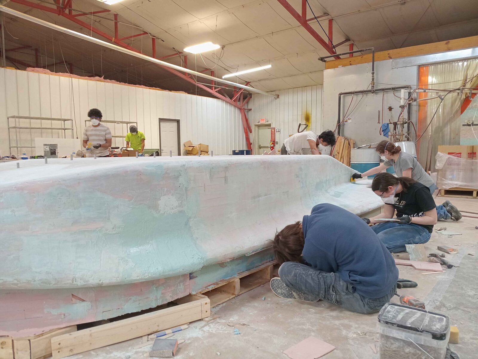
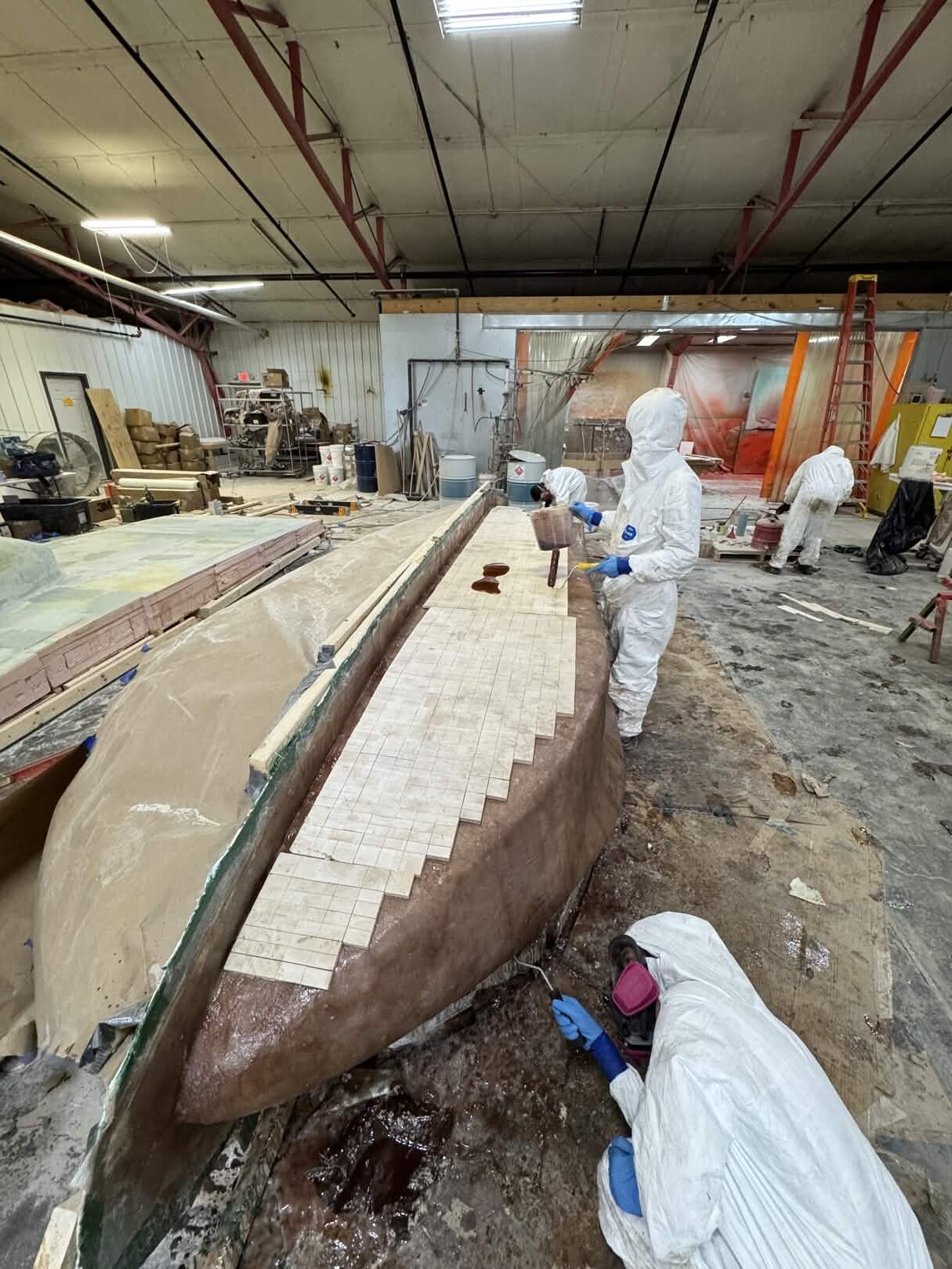
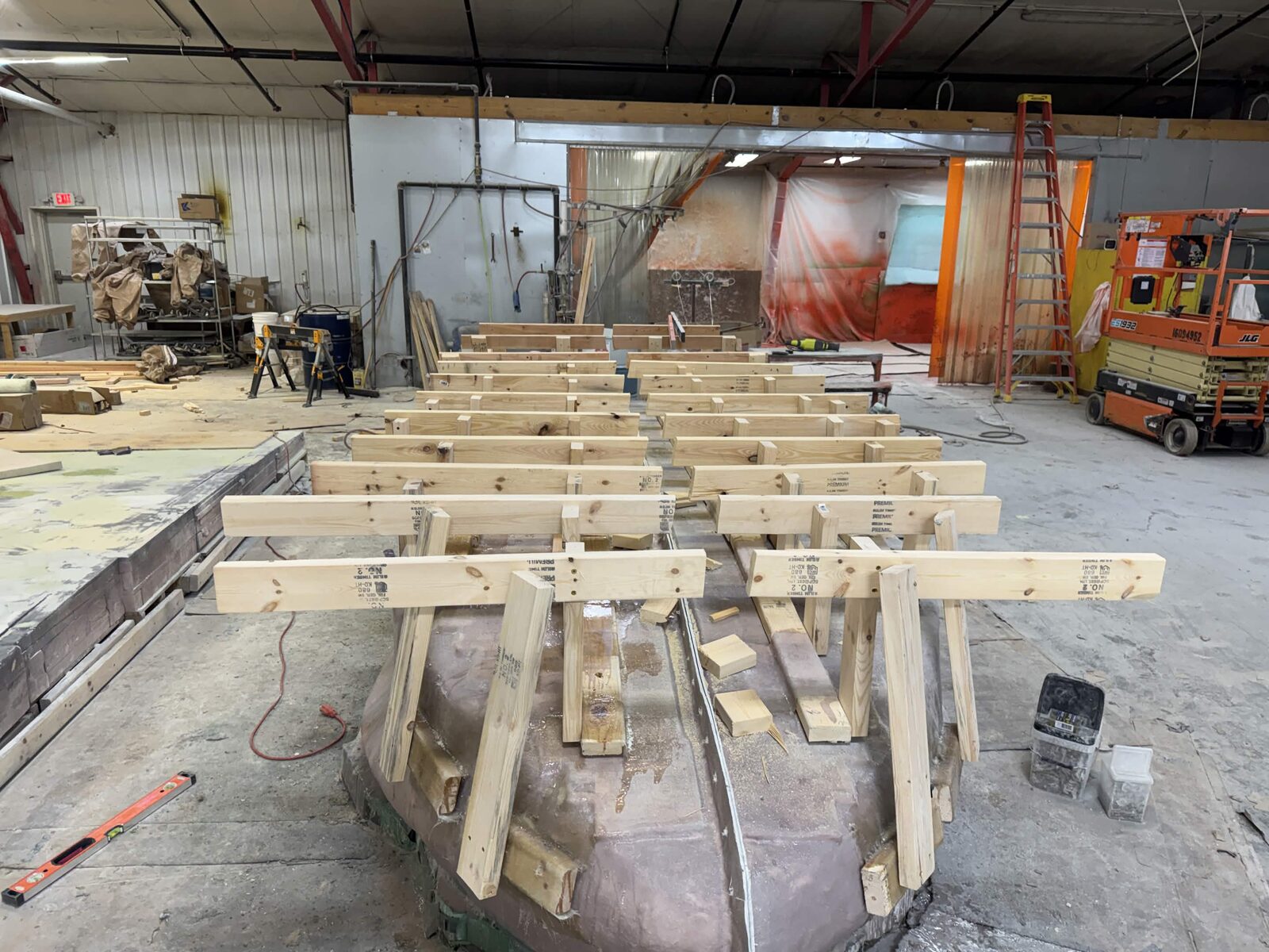
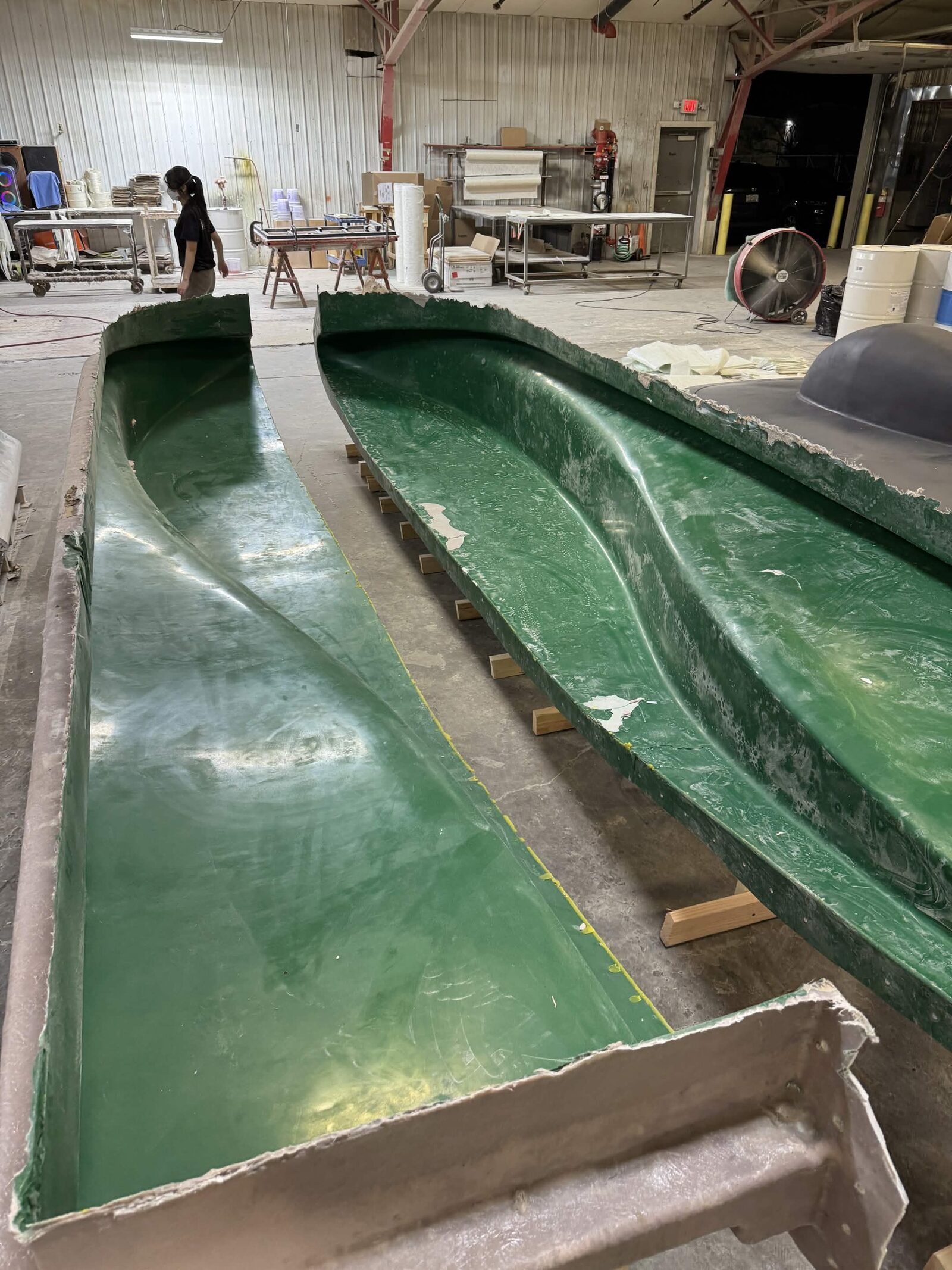
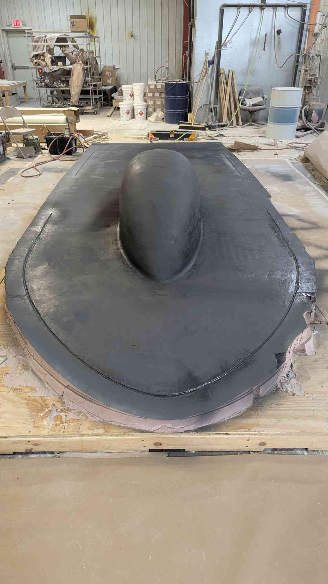
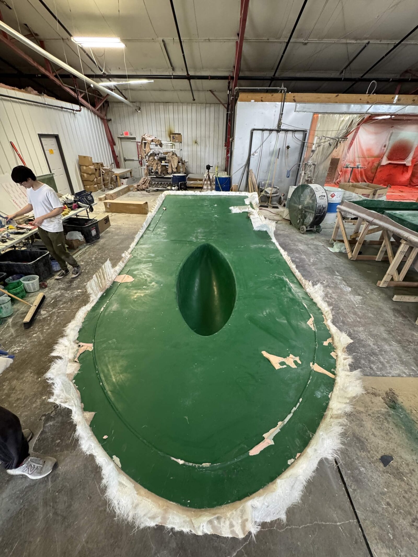
Sanding has opinions. Work the bondo at partial cure while it is still soft, sweep in large X patterns so you never dig a groove, and never press hard on a corner you spent a week earning. Let the paper do the work.
The fiberglass stage was all choreography. One person mixed resin, four rolled plies in rotating pairs, and one staged the next cut. Everyone else hunted air bubbles. They respawn the moment you look away.
Molds done. Then, finally, carbon fiber.
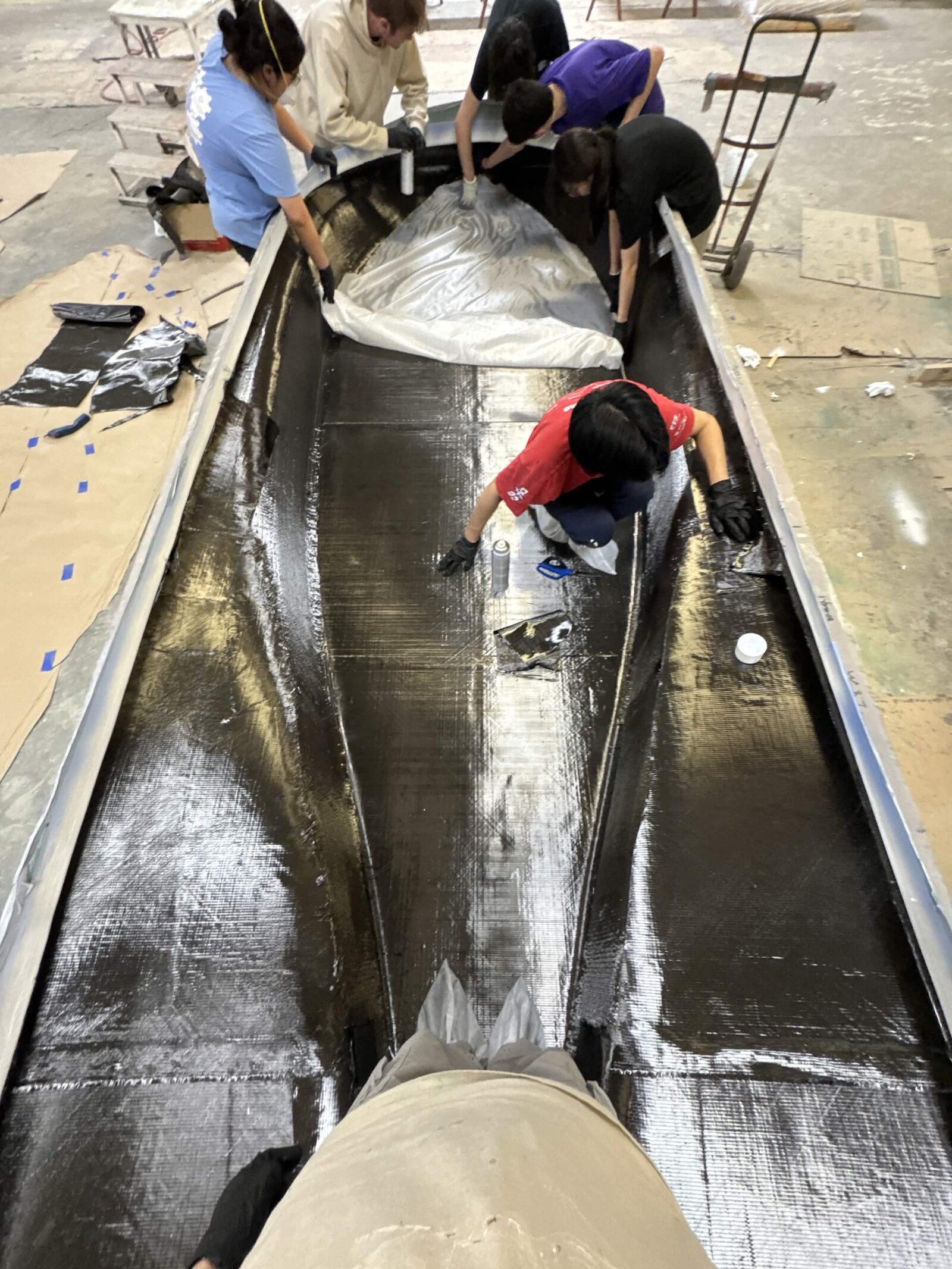
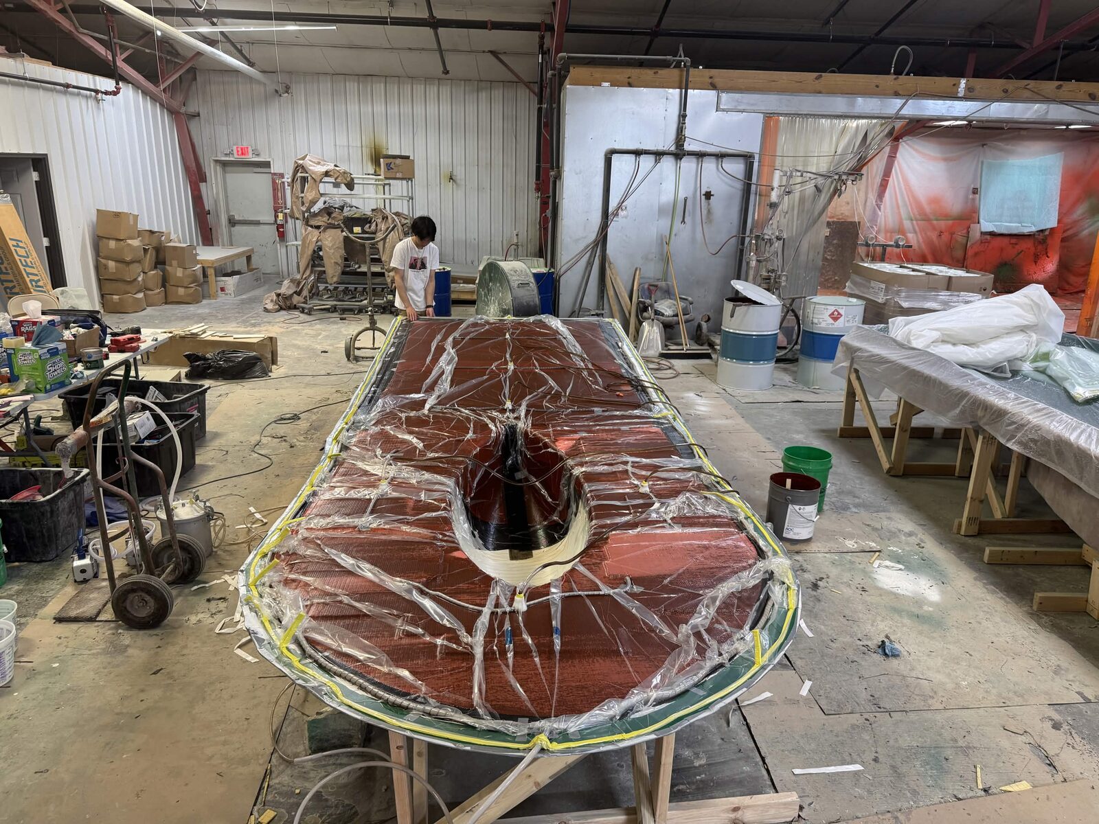
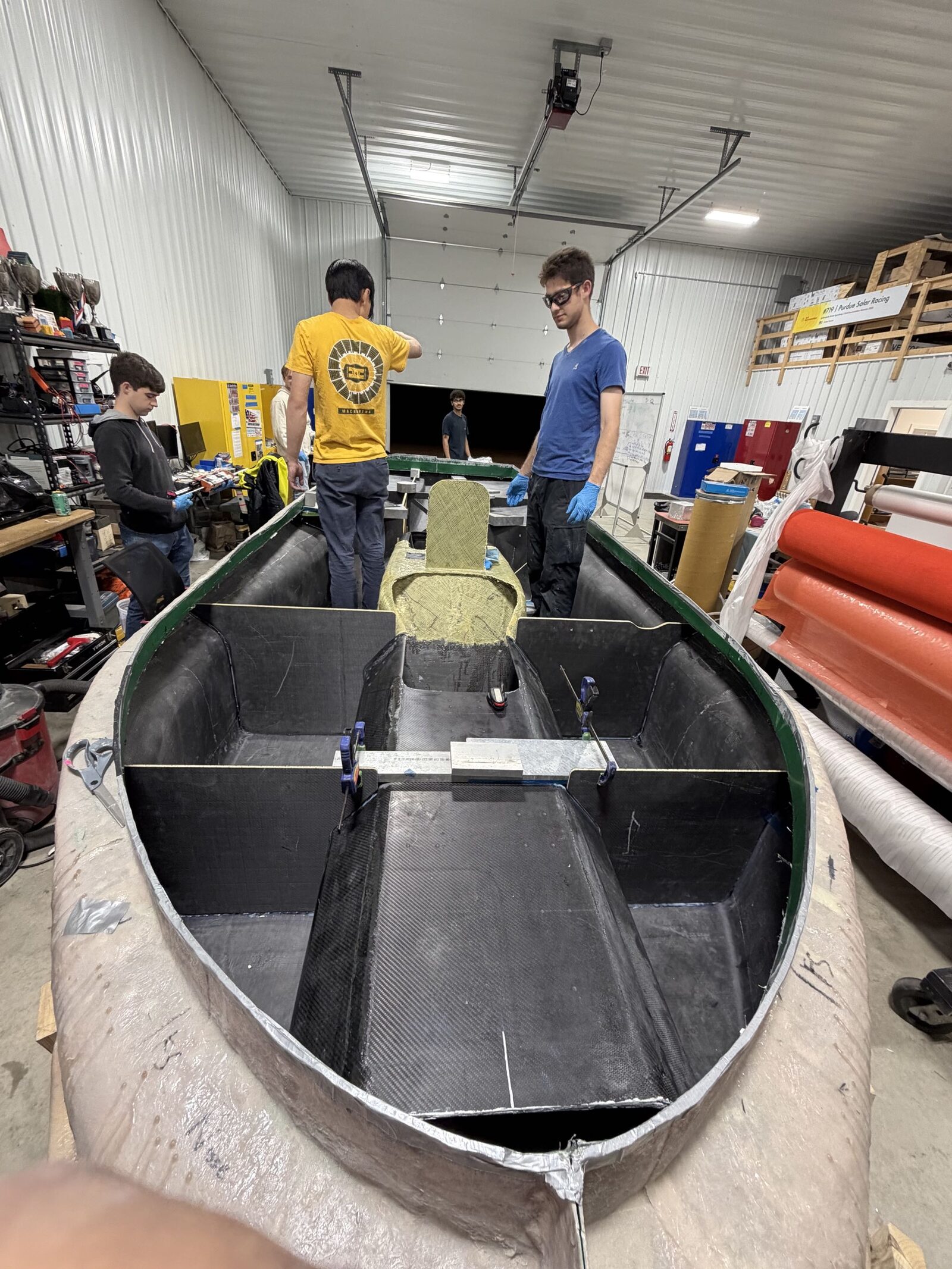
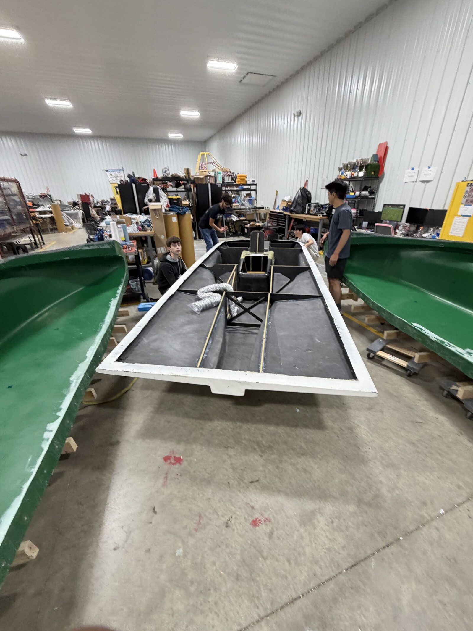
Vacuum assisted resin transfer molding (VARTM) rewards planning and punishes improvisation. Once the vinyl ester starts moving, there is no reaching in to fix anything. Because a dry spot found after cure is a redo, we watched the resin front creep across the part like nervous parents. Luckily, it came out with no major defects. From there the shell went to the structures team for integration, then into the finished car.
The Ultimate Takeaway
CFD is expensive. Each run swallowed eight hours on my own computer, which was good for nothing else in the meantime. Work at this scale really wants a supercomputer. It earned those hours, though. The catamaran was the trendy pick, but the bullet was the one we could package, build, and trust. Then we sanded from 32 grit to 1500 and turned a drag number on a screen into 20.25 kg of carbon fiber you can knock on!