Reconfigurable Pneumatic Actuator Array
May 202611 min read
- Soft Robotics
- Pneumatics
- 3D Printing
- Silicone Molding
- Abaqus
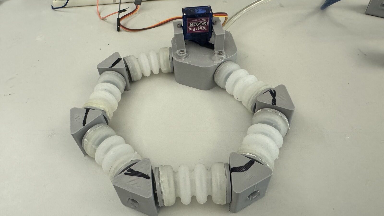
Two of us built a pneumatic bellow array that reconfigures on one air line per module, with adjustable servo valves at the nodes. Spring 2026 research at Purdue’s Robust and Adaptive Design (RAAD) Lab.
- Owned the connector node end to end: CAD, printing, Arduino servo control, bench testing.
- Co-developed silicone molding: a material bake-off landed on Ecoflex 00-50, 19x softer than the printed baseline, cast bubble-free under vacuum.
- Bench results: over 1.5 cm extension per cycle at 10 psi, repeatable. The servo sets the pace.
- Found the bottleneck: a 1.5 mm air channel throttles multi-node chains. Pressure loss scales with 1/r^4, so the next fix is a 3 mm channel.
Making the bellows was easy. The 1.5 mm channel hole diameter was the bottleneck.
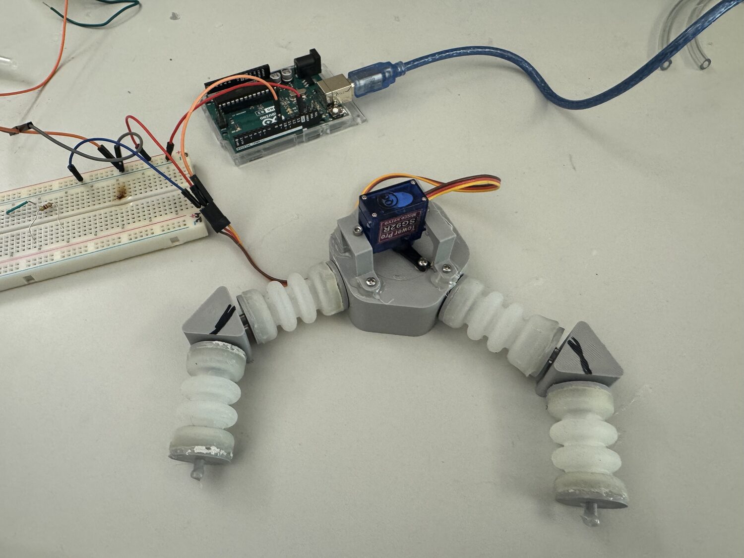
Undergraduate research at Purdue’s RAAD Lab with Prof. Laura Blumenschein, spring 2026. My partner, Ryan Wang, owned bellows fabrication. I owned the connector that decides where the air goes. The hexagonal ring up top is the prototype. Six nodes, six molded bellows, one air line, and for now a single servo.
The problem
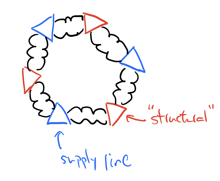
A bellow is a silicone accordion. Pump air in and it stretches. Robots built from bellows flex instead of hinge, which is why soft robots can grab things a rigid claw would crush. Most arrays fix each bellow’s job at assembly. The textbook fix is one regulator per bellow. Six bellows, six regulators, six lines. The plumbing is a hairball. Our goal was one supply line and a small servo valve at each node. A node’s role becomes a control decision tha can be adjusted while the robot runs.
The research behind it
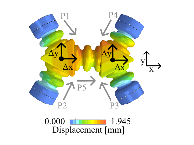
The lab had already characterized a lone bellow as a simple spring with known constants. It had also built a physics-informed neural network, or PINN, which forecasts a five-actuator system in 45 seconds instead of 5.5 hours. Our Abaqus bellow models feed that pipeline. The point is speed. Hardware that reconfigures in seconds is pointless if every new layout costs an overnight simulation.
My role
- Owned the connector node from concept through bench testing.
- Co-developed the silicone bellow molding: the mold, the materials, the bubble-free casting recipe.
- Started Abaqus models of the bellows, picking up the lab’s single-actuator thread.
- Sized the design with the lab’s spring constants, k_s ≈ 2.71 N/mm and k_θ ≈ 19.31 N/rad, the paper’s torsional factor.
The targets were one regulator and one inlet for up to 12 bellows, two outlets per node, and 5 to 10 psi. A car tire sits at 35.
The connector
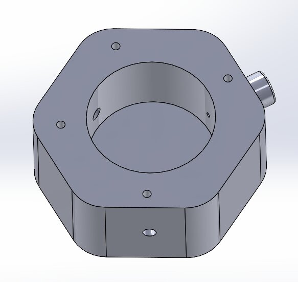
A hexagonal body with one inlet and two outlets. Inside sits a rotating cylinder, a revolving door for air, with one curved channel through it. The servo spins the cylinder until the channel meets outlet A or B. A U-bracket pair pins the servo down so it twists the valve instead of itself.
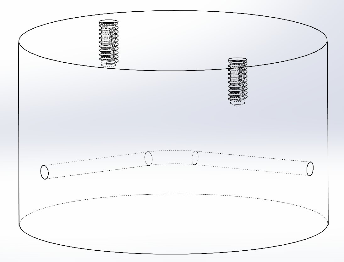
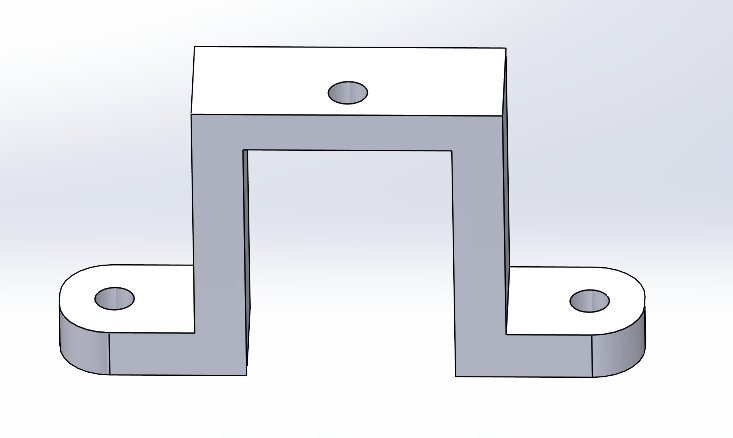
Two design calls worth explaining:
- A single-channel cylinder. An early T-shaped path fed both outlets at once. a servo error of a couple degrees changed which side got more air. One channel gives a clean A/B switch with a brief all-closed moment between.
- Resin print the cylinder, filament print the rest. The cylinder rotates inside the body and carries the air, which is why its surface finish matters. Filament ridges made a PETG cylinder bind and leak. Resin (Formlabs Clear v4) comes out glassy, spins freely, and seals in the press fit. The body and brackets only carry loads, a job cheap filament prints do fine. Control is deliberately dumb. An Arduino sweeps the servo open-loop between
36°and165°, holding 3 seconds at each.
Molding the bellows
Printed Elastic 50A bellows were too stiff to move much. We pivoted to cast silicone, the material effects studios mold fake skin from. We ran a bake-off of the Ecoflex suite:
| Material | Young’s modulus (stiffness) | vs. Elastic 50A |
|---|---|---|
| Elastic 50A (printed) | 1.59 MPa | baseline |
| Dragon Skin 20 | 0.338 MPa | 4.7x softer |
| Ecoflex 00-50 | 0.083 MPa | 19x softer |
Lower modulus means stretchier, and stretchier means more motion per psi. Ecoflex 00-10 was too floppy to hold a shape. Dragon Skin trapped bubbles that leaked. Ecoflex 00-50 sat in the sweet spot. The process that finally worked was a two-part, three-cavity mold with vent holes, resin-printed cores, a pour without de-bubbling, then a near-total vacuum until the big bubbles stop. Any bubble you trap now is an air leak later.
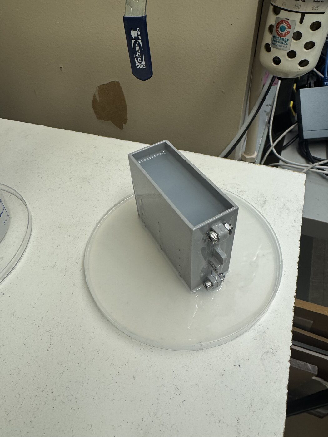
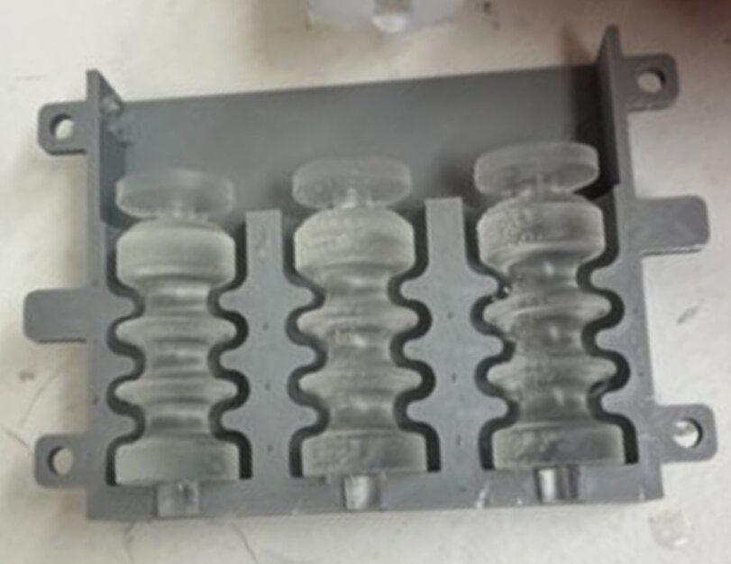
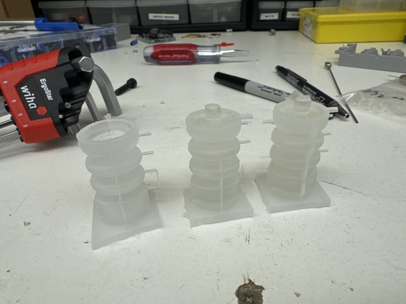
The payoff was a bubble-free bellow that stretches roughly 75% of its resting length. Ecoflex is so soft the bellows barely hold their shape. The glued-on end caps do double duty, part skeleton, part plug for the connector.
What broke, and what I changed
| Tried | Problem | Fix |
|---|---|---|
| Two-channel cylinder | ambiguous mid-rotation states | single channel, clean A/B |
| Pololu 12V gearmotor + encoder | the encoder (position sensor) lost count at low speeds | open-loop hobby servo |
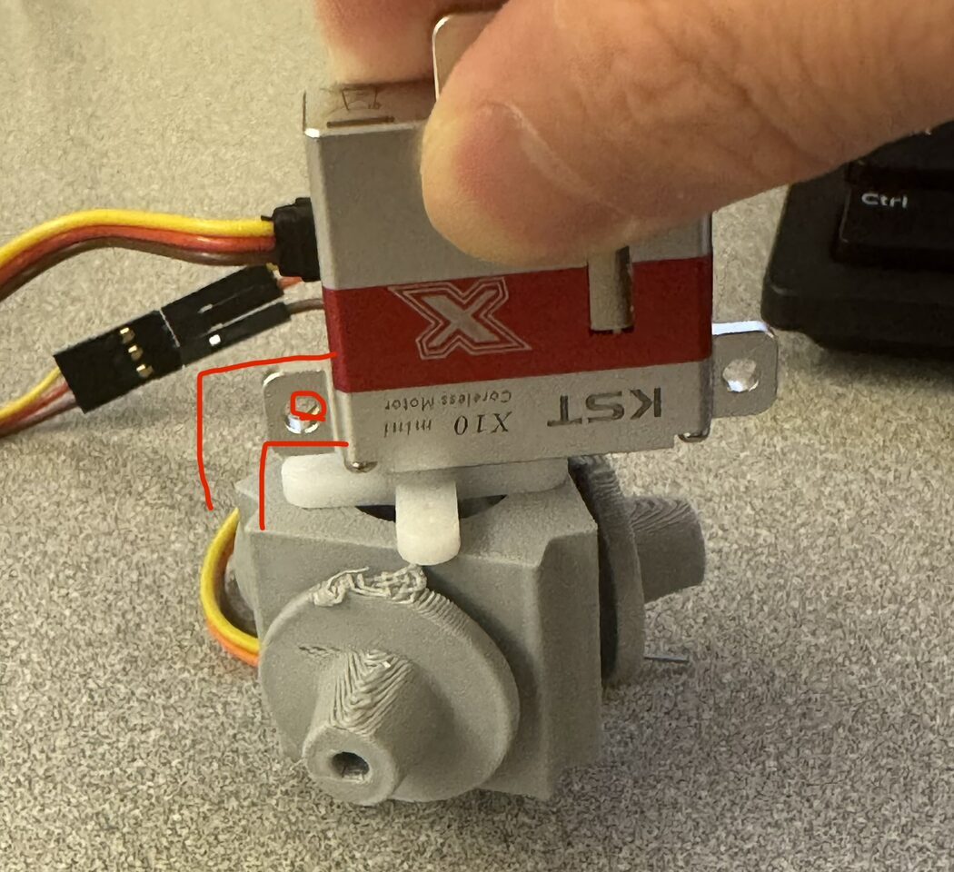
| KST X10 servo | only 100° of travel, can’t reach both outlets | TowerPro SG92R (180°) |
| PETG rotating cylinder | layer ridges caused friction and leaks | resin-printed Clear v4 |
Using the KST X10 servo taught me a valuable lesson. I designed the whole body around it and only then found that 100° of travel cannot reach both outlets. One full design-print-fit cycle, gone, because I did not check the datasheet.
Testing
One node, two bellows, air held at one set pressure, valve flipped back and forth.
| Inlet pressure | Extension per cycle | Verdict |
|---|---|---|
| 10 psi | > 1.5 cm, both outlets, repeatable | clean alternation |
| 5 psi | > 1 cm, reduced but still readable | practical floor |
The bellows fill in under a tenth of a second. A servo swing takes about a third of a second, which makes the motor the pacemaker. The valve concept works.
The bottleneck
With the valve proven, I chained more bellows onto one inlet. The first inflates well while the ones downstream barely twitch. The culprit is one hole. Where the inlet tubing meets the connector, the internal air channel pinches down to 1.5 mm, which leaves every bellow downstream fighting for air through the same skinny passage.
Hagen-Poiseuille, the equation to model smooth, steady flow through a narrow pipe, can be applied here. With radius in the denominator to the fourth power, a hole half as wide makes the air fight sixteen times harder. Anyone who has ground espresso too fine and choked the machine has met this law in person. I encountered this exact problem at my coffee shop job.
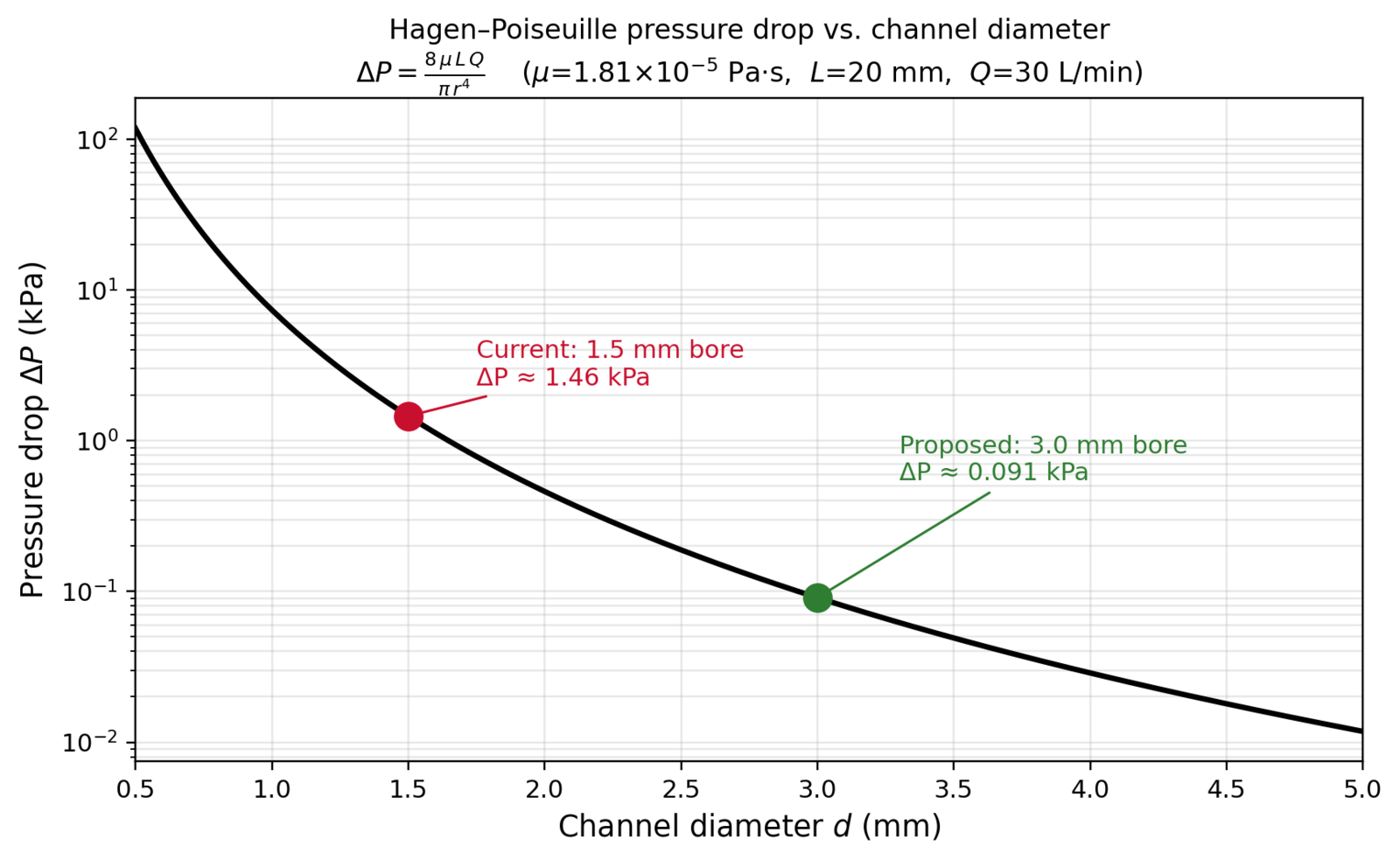
Widening the channel to 3 mm is the single highest-value change for the next build. After that come a position sensor, a three-outlet node for triangular networks, and a PINN hookup so new layouts get simulated before fabrication.
- One air line drives a two-outlet node.
- Servo switches cleanly between outlets.
- Alternating actuation held at both 5 and 10 psi.
- Scales past two bellows per inlet (the fix is the wider channel).
The Ultimate Takeaway
Fabricating the bellows was the easy part. The real engineering lived in the valve, the seal, and a 1.5 mm air inlet that quietly throttled the whole array. I will also remember to ALWAYS read the datasheet before designing around a part. And the bottleneck is rarely where the eye goes. Everyone watches the stretchy bellows and the spinning valve, but the ceiling of this robot was one skinny air passage.