Two-Stage Spur Gearbox for an Electric Go-Kart
April 202610 min read
- Machine Design
- Gears
- Shaft Fatigue
- AGMA
- CAD
- MATLAB
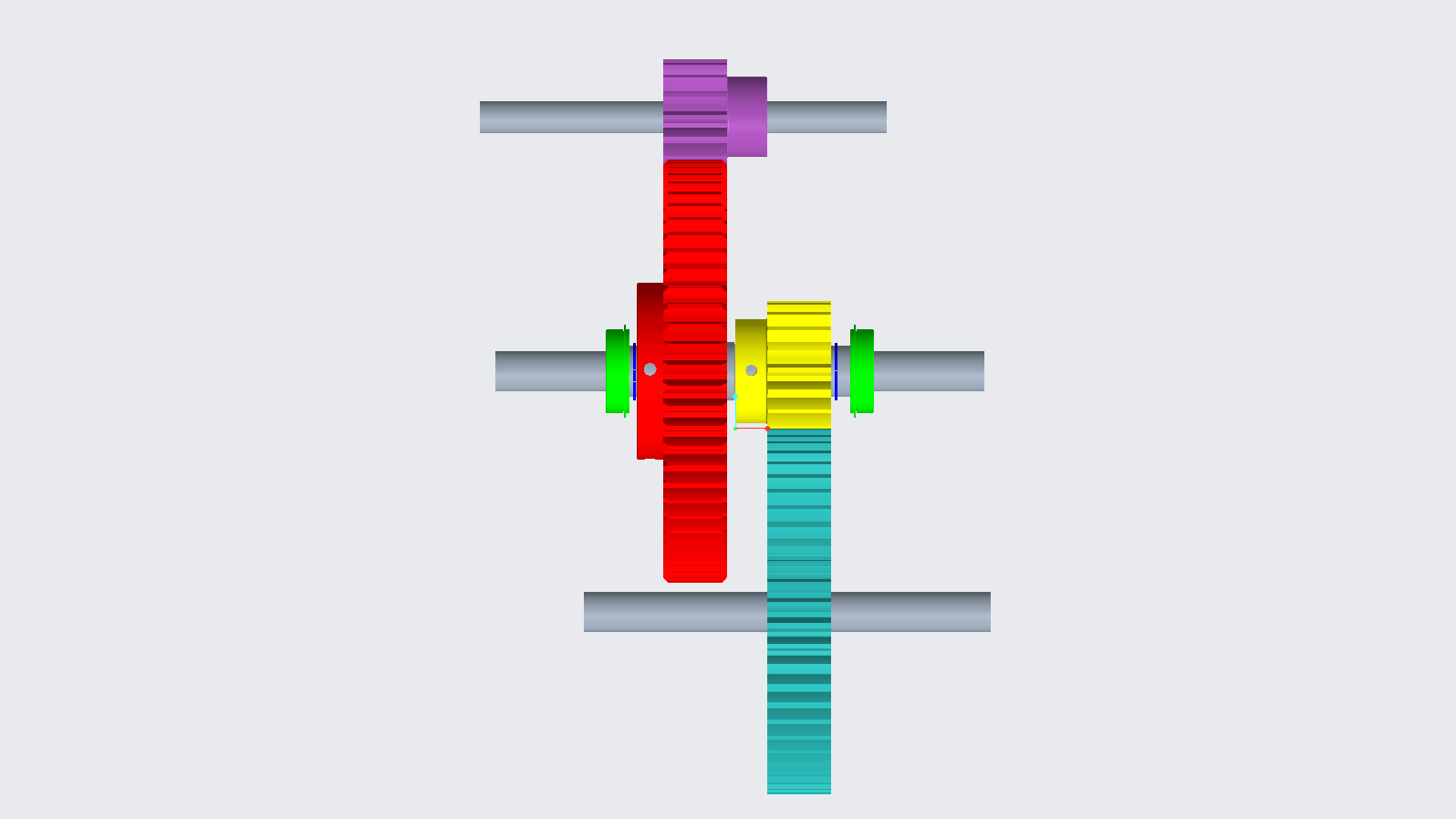
My independent project for the machine design course was a 20:1 two-stage spur gearbox for an electric go-kart. Most requirements came straight out of Shigley’s Mechanical Engineering Design textbook.
- Shaft first: found the spot fatigue punishes hardest, gear 3, and sized the shaft there with DE-Goodman. The gear bore clears the math by 0.77 mm.
- Module 4, 16/64/20/100 teeth: torque climbs from 315 to 6,300 inch-pounds.
- Every check passed with margin: shaft fatigue at FOS of 2.06 against a 1.5 target, AGMA tooth checks, bearings good for 91 million revolutions, keys at FOS of 6.4 or higher.
- Twelve MATLAB files, one master file controls them all. Change a tooth count and every safety factor regenerates.
Design for the worst spot in the machine first. Let that decision drive everything else.
Context
My final project for ME 354, Purdue’s machine design course (Spring 2026). Machine design is sizing real parts so they carry their loads for a lifetime without breaking. Every equation ran straight out of Shigley’s Mechanical Engineering Design, the thousand-page brick that has been settling “will this shaft break” arguments since 1963 (iykyk).
The task was to design the gear train that powers one wheel of an electric go-kart. A gearbox trades speed for twist the same way bike gears do. The motor spins fast but gently, while the wheel needs to turn slower with far more torque. Here are the specs:
- Input: 50 hp at 10,000 rpm, sportbike-redline speed.
- Output: 500 rpm, a 20:1 total reduction.
- Traction force: 300 pounds of push at each wheel.
- Intermediate shaft: exactly 12 in long, all gears in one plane.
- Goal: minimum gearbox depth. Pack the gear stack as tight as it can go.
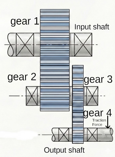
Where to start? The obvious move is to pick the gears first and hope the shaft cooperates. But the shaft is the part fatigue kills, the way a paperclip snaps after enough bending back and forth. A spinning shaft bends slightly on every revolution, millions of times a day. So I found the spot the loads punish hardest, sized it to last forever, and let that decision drive the gear selection.
Picking the Module and Teeth
The 20:1 reduction splits into two stages of spur gears, 4:1 then 5:1. Torque climbs from 315 inch-pounds at the input to 6,300 at the output. That is 525 lb·ft, more twist than the V8 in a typical full-size pickup makes.
Gear teeth come in standard sizes called the module, in millimeters. Bigger module, beefier teeth. I compared modules 3 and 4 at the gear-3 seat, the patch of shaft that gear clamps onto:
| Module m (mm) | Gear-3 force (lbf) | First-pass shaft diameter (mm) |
|---|---|---|
| 3 | 1067 | 36.5 |
| 4 | 800 | 33.7 |
Module 4 wins. Bigger teeth means a larger gear that pushes at a wider radius with less force. Less force means less shaft, which keeps the gearbox shallow. Those diameters are early screening estimates. The real number comes out smaller once the shaft layout is pinned down.
Final tooth counts ended up at 16/64/20/100, every one above Shigley’s interference floor, the rule that keeps small gears from gouging each other as they roll. Three of the four are stock MISUMI catalog parts. Gear 3 came with induction-hardened teeth, for reasons about to become obvious. Gear 4, at 100 teeth, would be made in-house.
Sizing the Intermediate Shaft
The 12-in shaft carries two gears, two bearings, and the shoulders, keys, and retaining rings that lock each part in place. Mechanically, it is a plank across two sawhorses, held up by a bearing at each end and pushed on by the gears in the middle. I split the gear forces into vertical and horizontal components, solved each direction, then recombined them.
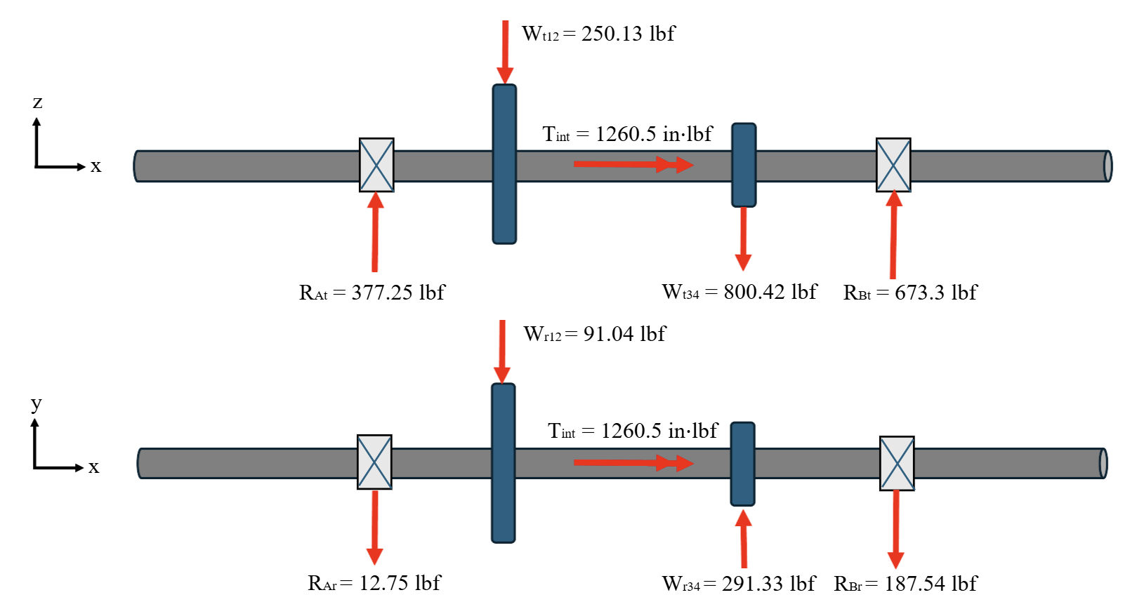 The driving push (top) spins the shaft while the separating push (bottom) shoves the gears apart. Torque enters at one gear and leaves at the other. Only the stretch between them carries torque.
Add up the bending from the driving push (1040 in·lbf) and the separating push (290). Everything points at one spot:
Gear 3 is the critical location. It takes the hardest bend and the full twist at once. If the shaft survives here, it survives everywhere.
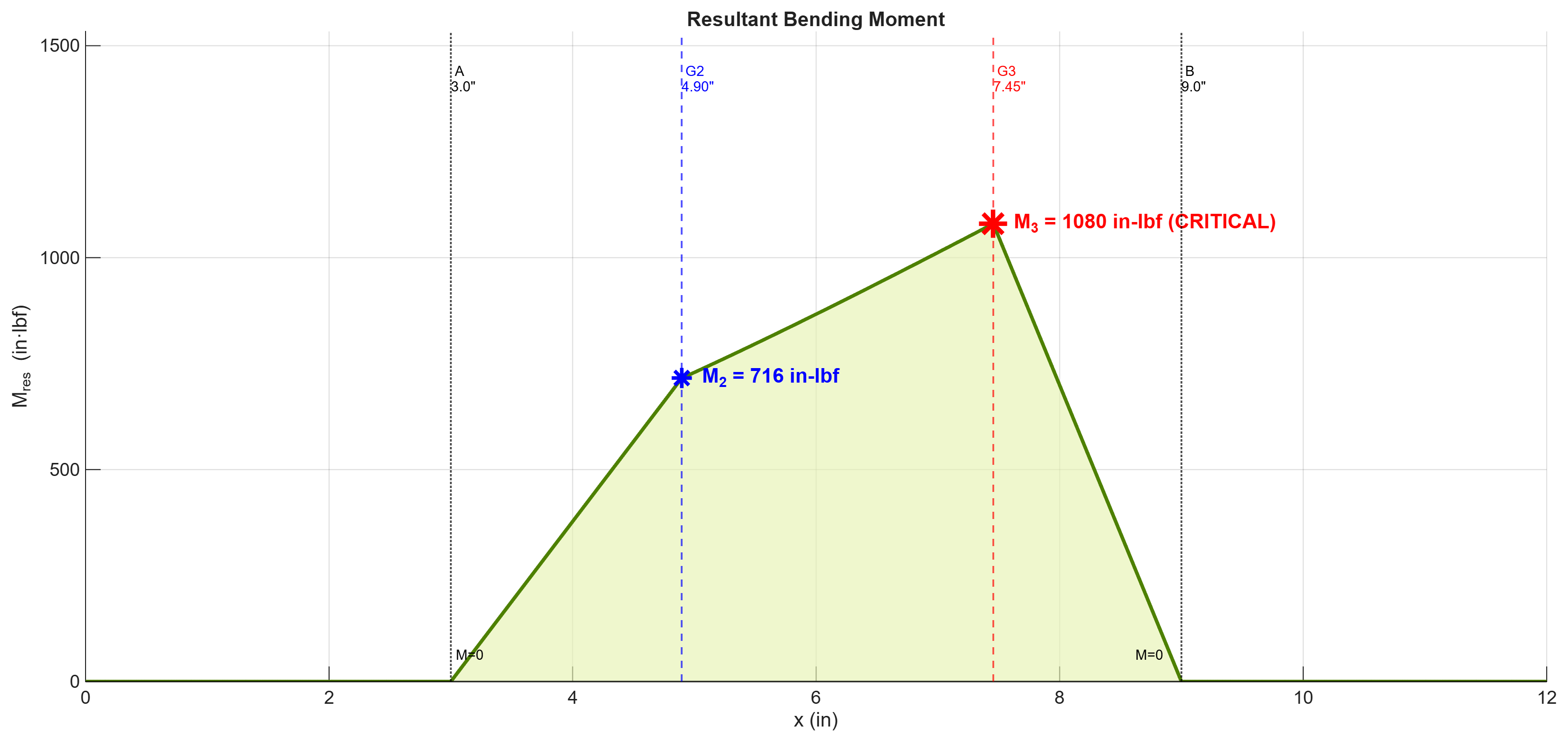 Combined bending moment along the shaft. The peak sits right at the gear-3 seat, marked critical.
From that load, the DE-Goodman equation returns the thinnest shaft that reaches infinite life. Infinite life means it never fails from fatigue, no matter how many times it spins:
I needed 31.23 mm. The catalog gear’s bore, the hole through its center, is 32 mm. That is 0.77 mm of margin, which is tight on purpose. The bore only has to clear the math. Every millimeter of extra shaft diameter ripples outward into bigger bearings and a deeper gearbox.
Sharp corners concentrate stress, so every key slot, shoulder step, and ring groove got its own Neuber-corrected check. The worst is the gear-3 key slot at , about twice its design load and comfortably past the 1.5 target.
Verifying the Whole Thing
The shaft is only one part. Everything pressed, keyed, or meshed onto it gets its own check:
- Gear teeth (AGMA). The industry’s standard checks for the two ways teeth die, snapping at the root and pitting on the contact faces. Both pass for every gear. The thinnest margin is gear-1 contact at , a 19% cushion, because that mesh slides past at 6,600 ft/min (75 mph) and AGMA charges a penalty for speed. Gear 3 is where the hardening pays off. Its teeth see about 111,000 psi against a 170,000 psi rating. Plain steel, rated for only 105,000 psi, would not survive there.
- Bearings. MISUMI B6205ZZNR deep-groove ball bearings at both ends of the shaft. After the first stage’s 4:1 reduction, the shaft spins at 2,500 rpm. The harder-working right bearing is rated for 91 million revolutions, about 609 hours at full throttle. Plenty for a recreational kart.
- Keys. The 1045-steel blocks that lock each gear to its shaft. Checked against shearing and crushing. Every safety factor sits at 6.4 or higher, nowhere near the weak link.
- Press fit. Each bearing ring is fractionally smaller than the 25 mm seat it presses onto. That squeeze is what grips the shaft. The fit stayed snug across the whole manufacturing tolerance range. The stress it adds is a small fraction of what the steel can take.
All of it is scripted in twelve MATLAB files under one master run file. Change a tooth count and every force, safety factor, and diagram downstream regenerates. When early gear candidates failed the shaft check, which happened more than once, the re-run took seconds instead of an evening of tedious recalculations.
Bringing It Into CAD
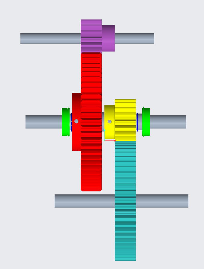
Every dimension in the drawings, down to each rounded corner and key slot, traces back to a number above.
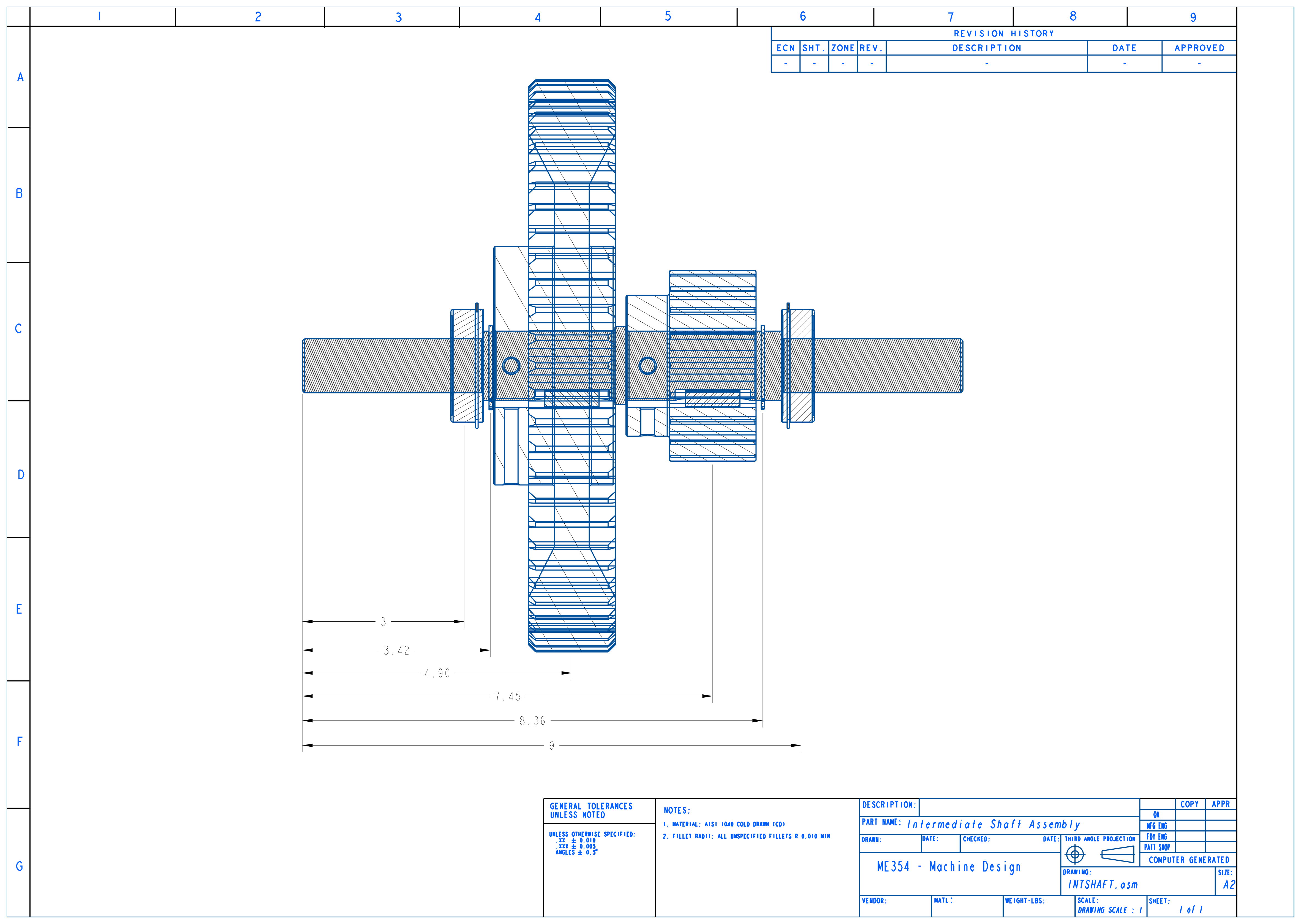
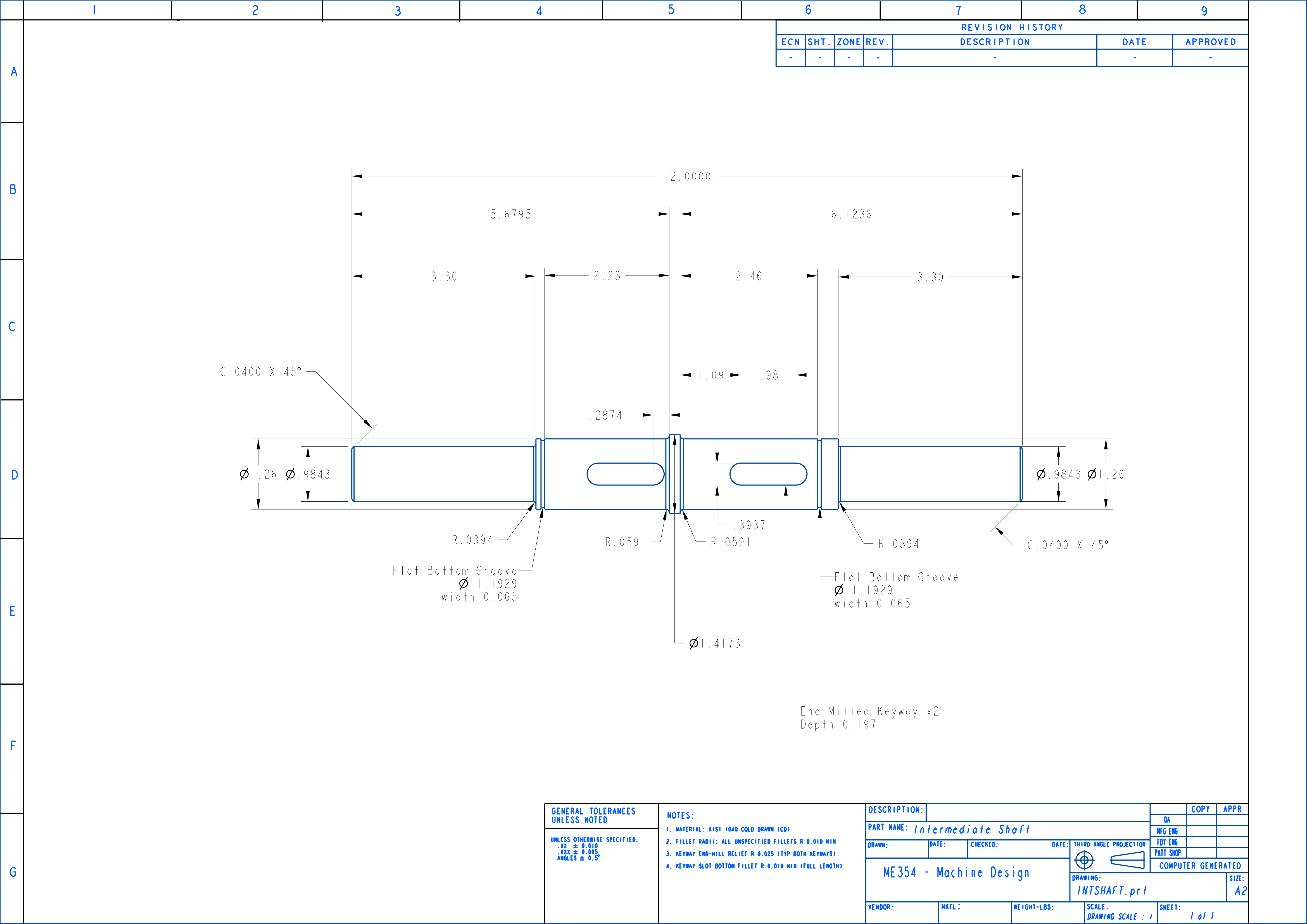 The bare shaft, fully dimensioned, with stepped diameters, keyways, ring grooves, and bearing shoulders.
Results
Every check, in one table. is the shaft fatigue safety factor, and the AGMA factors for tooth bending and surface stress, the revolutions 90% of bearings survive. A FOS of 1.0 survives on paper. Everything here clears with room:
| Check | Requirement | Result | |
|---|---|---|---|
| Total ratio | 20:1 | 4 × 5 = 20 | |
| Shaft fatigue | 2.06 at gear 3 | ||
| AGMA bending | ≥ 2.55 | ||
| AGMA contact | ≥ 1.19 | ||
| Bearing life | rev | 91 Mrev (609 h) | |
| Key stress | ≥ 6.4 |
What I’d Change Next Time
- Sized at steady state only. A real kart sees launch shock and braking. A production pass would add a dynamic overload factor to cover the shock loads.
- Gear-1 contact is the soft spot. Hardening gear 1’s teeth like gear 3’s, or widening its face, would buy back that thin 1.19 margin.
- Losses ignored. Mesh and bearing friction eat 2 to 5% per stage.
The Ultimate Takeaway
Find the one spot in the machine that has it worst and design for it first. Here that was gear 3. I sized the shaft there, the bore cleared by 0.77 mm, and every downstream check passed with room to spare. Shigley has an equation for every way a part can fail. The design work is knowing which one to run first.