Three-Band Analog Audio Equalizer
May 20258 min read
- Analog Circuits
- Audio
- Op-Amps
- LTspice
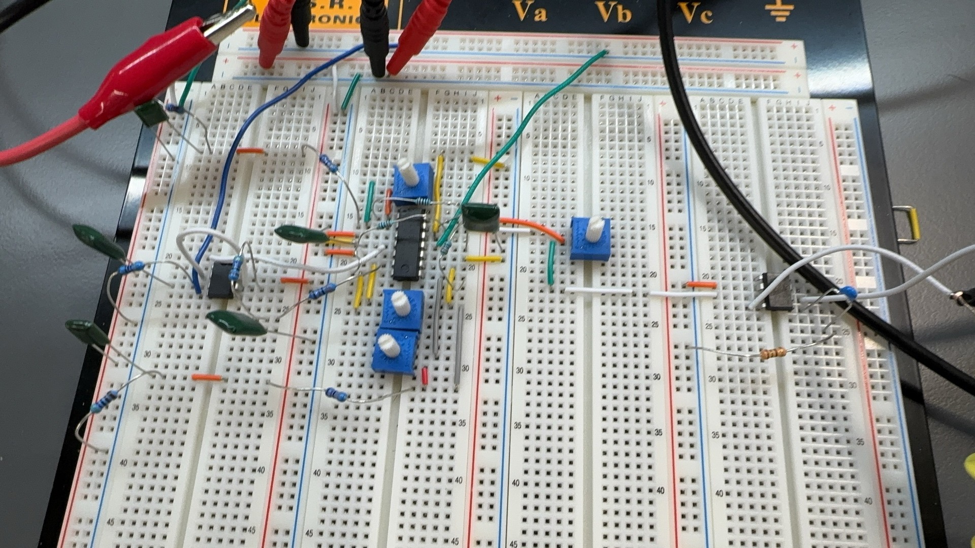
A three-band audio equalizer that adds bass, mid, and treble knobs to a line-level signal, built entirely from a standard intro analog lab kit.
- Four-stage path: passive RC filters split the signal into bands, LM324 op-amp stages set each band’s gain, a summing stage recombines them, and an LM386 drives the speaker.
- Every spec met: corners within 7% of 320Hz and 3.2kHz, mute leakage around 0.2mV against a 15mV budget, 0.85W into 8Ω versus the 0.4W floor.
- Verified stage by stage: frequency response on the oscilloscope for each filter, then sine sweeps, then real music.
- Bypass capacitors and a snubber: the parts standing between clean audio and phantom oscillation.
Four RC filters and a pile of op-amps cleared every spec.
Context
My final project for the introductory analog circuit course ECE 2007 (Spring 2025), built solo from schematic to bench test. The task was to take a line-level audio signal (roughly what a headphone jack puts out), add bass, mid, and treble knobs, and drive a speaker.
Every part had to come from the standard lab kit, which left almost no wiggle room in component selection. The specs:
- -3dB corners, the frequencies where the bands hand off to each other, at 320Hz and 3.2kHz within ±10%.
- ±12dB of boost or cut per band (roughly four times the signal level, up or down), without shifting those corners.
- <15mV ripple, the volume gap between bands, with all bands set equal.
- <15mV output when muted.
- >400mW into an 8Ω speaker across 100Hz to 10kHz (loud enough to fill a room from a bookshelf speaker).
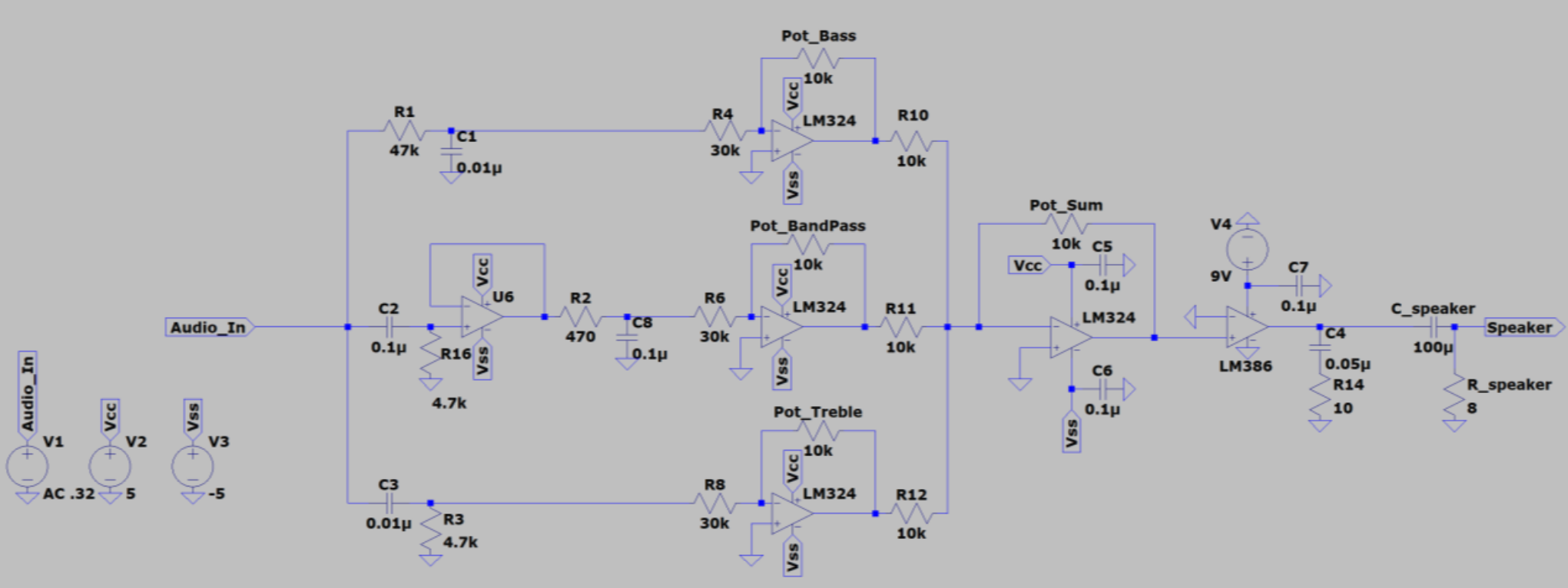 The complete schematic in LTspice. Every part and value matches the breadboard 1:1, which let the bench confirm the simulation.
How It Works
The signal takes a four-step route to the speaker: split, shape, recombine, amplify.
-
Split. Three passive RC filters carve the input into bass, mid, and treble. Each filter is just a resistor and a capacitor. Frequencies on the wrong side of its corner get blocked. That corner comes straight from the first-order cutoff equation:
-
Shape. Each band runs through an LM324 gain stage whose amplification is set by a 10kΩ potentiometer. Gain is the feedback resistor divided by the input resistor, . Turn the knob and that band gets louder or quieter, from silent up to full boost. The tuning never shifts because volume and corner frequency are set by different parts of the circuit.
-
Recombine. A fourth LM324 merges the three bands back into one signal through matched 10kΩ resistors. So when every knob is centered, the music comes out exactly as it went in. The same stage’s feedback pot doubles as the master volume. One chip, two jobs.
-
Amplify. Op-amps are good at shaping signals but too weak to move a speaker. An LM386 power amp handles the final push. It is a decades-old chip that still ships inside guitar practice amps.
These are the values that set each band, picked so the calculated cutoffs landed inside the ±10% window:
| Band | R | C |
|---|---|---|
| Low-pass (bass) | 47kΩ | 0.01µF |
| Band-pass, lower edge | 4.7kΩ | 0.10µF |
| Band-pass, upper edge | 470Ω | 0.10µF |
| High-pass (treble) | 4.7kΩ | 0.01µF |
320Hz to 3.2kHz is nearly the exact passband of an old telephone line. The mid knob is, in effect, a volume control for the human voice!
Design Choices
- A buffer inside the mid band. The mid filter is two filters chained together. Wiring them directly makes the second one drag the first one’s tuning off target. A unity-gain buffer between them fixes that. It passes the signal along while letting neither side disturb the other. Each corner stays where the equation says it should be.
- 30kΩ input resistors on every gain stage. Each band’s volume is its feedback pot divided by that 30kΩ, so a knob sweeps smoothly from dead silent up to a hard ceiling. The spec’s ±12dB of adjustment fits inside that sweep. The cutoff frequencies stay untouched no matter where the knob sits.
- 0.1µF bypass capacitors on every supply pin. Fast and easy insurance against noise sneaking in through the power lines. Twenty cents of ceramic now, or one afternoon chasing a phantom oscillation later (which is exactly what happened to me).
- A 0.05µF + 10Ω snubber on the amp output. A snubber is a resistor and capacitor across the output that calms the amp at high frequency. Speakers push back harder as frequency climbs, and past a point the amp gets twitchy. Two parts kept the output stable at high frequency.
Results
Each stage got a frequency response analysis on the oscilloscope: sweep a test tone from low to high and plot how the circuit responds. Then the full chain got sine sweeps, and finally real music through the speaker.
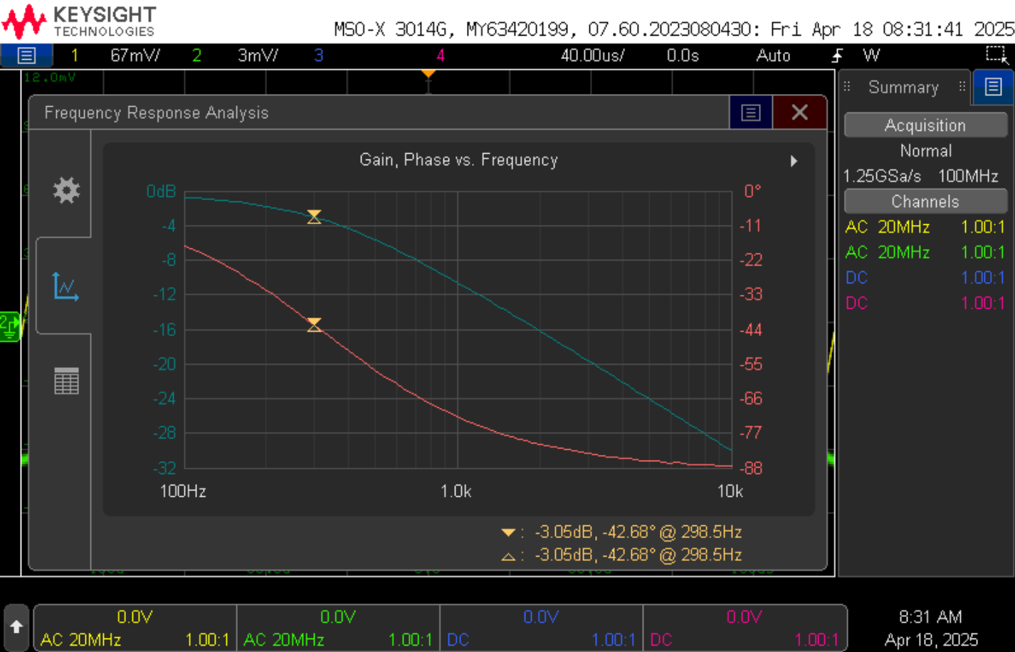 The low-pass corner landed at 298.5Hz, 6.7% below the 320Hz target and well inside spec.
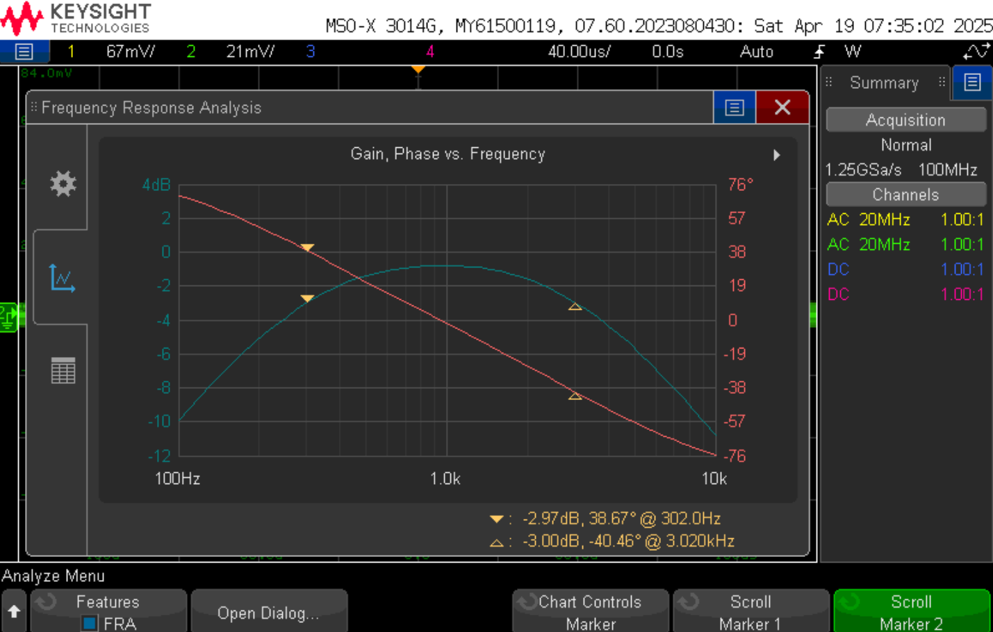 The mid band’s corners landed at 302Hz and 3.02kHz, and the region between them stays level within ±1dB. The isolation buffer did its job.
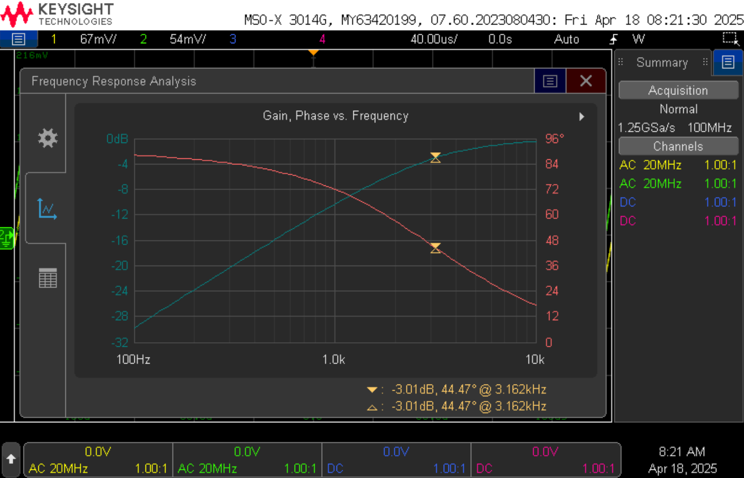 The treble corner landed at 3.162kHz, just 1.2% under the 3.2kHz target.
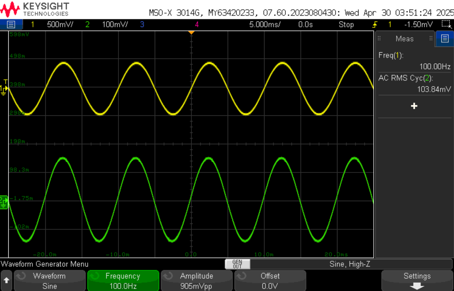 Full boost at 100Hz measured 103.84mV against the design’s own 100mV ±10% output target.
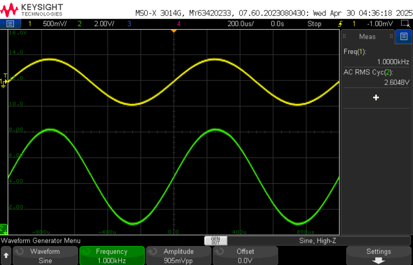 The LM386 swinging 2.6V RMS (the steady-power equivalent of the swinging signal) across the 8Ω load with every knob wide open.
The final scorecard, spec by spec:
| Spec | Target | Measured | Status |
|---|---|---|---|
| Corners | 320Hz / 3.2kHz ±10% | all within 7% | |
| Mute output | <15mV | ~0.2mV, about 1/1500th of the input | |
| Full-boost level | 100mV ±10% | 93 to 104mV across bands | |
| Ripple (volume spread between bands at full boost) | <15mV | 10.7mV | |
| Output power | >400mW into 8Ω | 0.85W from 2.6V RMS |
No plot can show the last result. The three knobs work independently. No audible crosstalk between bands.
What I’d Change Next Time
Three of the four corners came in 5.6 to 6.7% under the 320Hz and 3.2kHz targets. Against the values the kit parts actually calculate to, 339Hz and 3.39kHz, the drift is closer to 12%. That traces to the kit’s capacitors and the resistors stacked with them. Every corner landed low, which is what oversized capacitance looks like. Cheap ceramic capacitors drift well past their marked tolerance (the treble corner, 1.2% under target, evidently drew a good one). Sallen and Key published their filter topology in 1955. It is still standard. A second build could use 2% polypropylene capacitors and second-order Sallen-Key filters for sharper band edges.
The Ultimate Takeaway
Textbook equations, a handful of op-amps, and a pile of resistors will genuinely get you a working equalizer. Every spec passed. What actually leaked through on mute was over 1,500 times quieter than the input, faint enough to vanish into the oscilloscope’s own noise floor. Hearing first-order math shape real music is exactly as satisfying as it sounds, coming from a mechanical engineer!