Dual Clock-Tower Pen Holder
December 20259 min read
- DFM/DFA
- Laser Cutting
- Sheet Metal
- CAD
- SolidWorks
- Rapid Prototyping
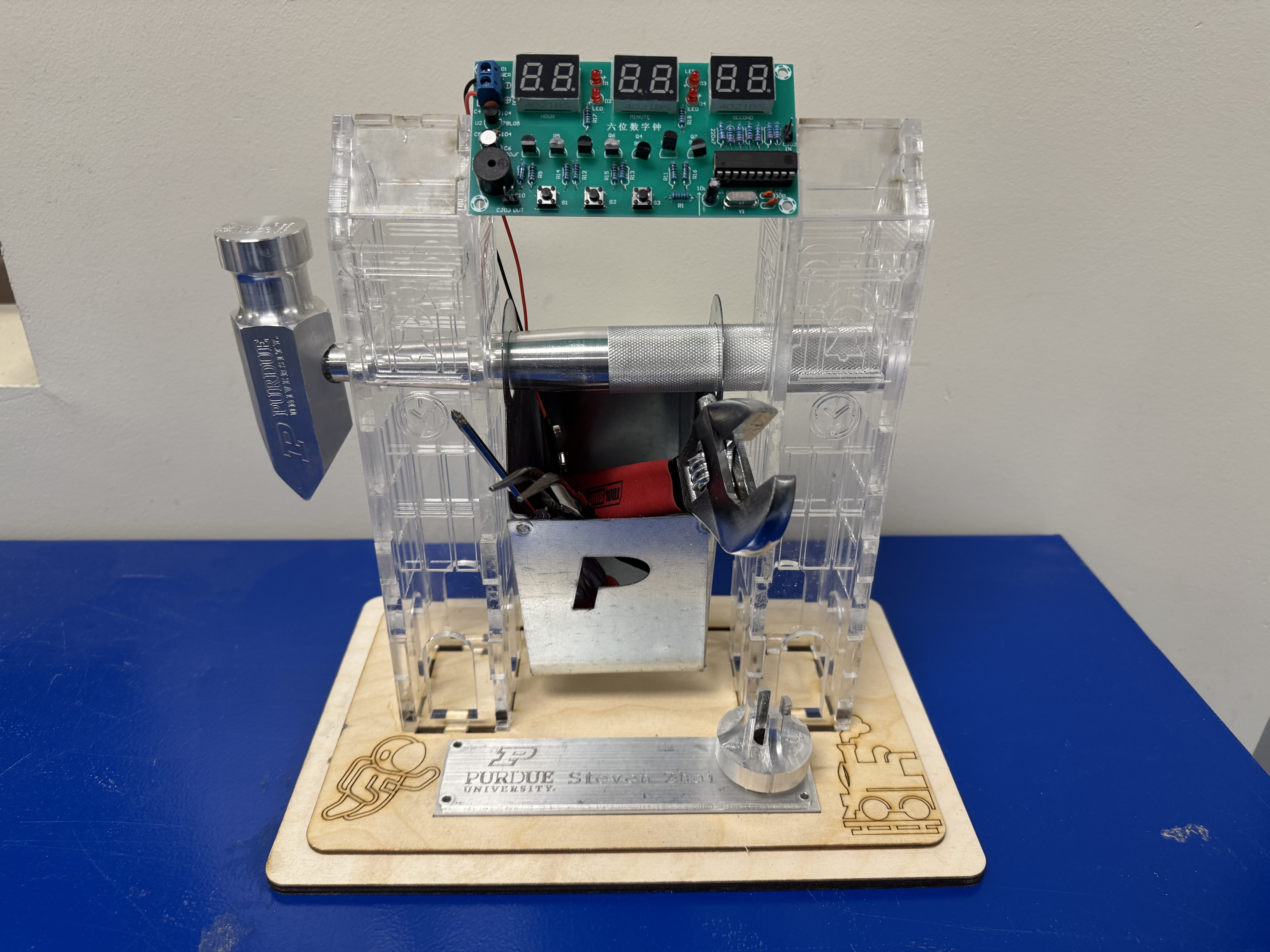
Final project for Purdue’s intro manufacturing course with my partner, Oliver Zeng. A dual clock-tower pen holder styled after the Purdue Bell Tower. I co-led CAD and drawings, ran the acrylic cuts and glue-up, and owned the bill of materials.
- Function first: a function tree and a weighted matrix picked the double tower from three concepts.
- Zero fasteners: tab-and-slot joints and glue, slots drawn 0.1 to 0.2 mm undersize so the kerf leaves a press fit. Design for Assembly (DFA) score 45/60.
- Built in about three hours from laser-cut plywood and acrylic plus a bent sheet-metal bracket.
- Calipered 30+ slot and hole positions, nearly all within a few tenths of a millimeter.
Tabs do the work of screws. The laser holds tolerance.
Context
My final for ME 264 (Fall 2025). Oliver and I had one requirement we could not design around, which was that the course hammer had to be on display. For extra funsies we gave it the most academic-sounding name we could manage. “Towards Embodied Agentic Classifier, Leveraging Conceptually Gravitational Over-actuated Systems.” It is essentially a pen holder that swings.
The requirements for the final product were the following:
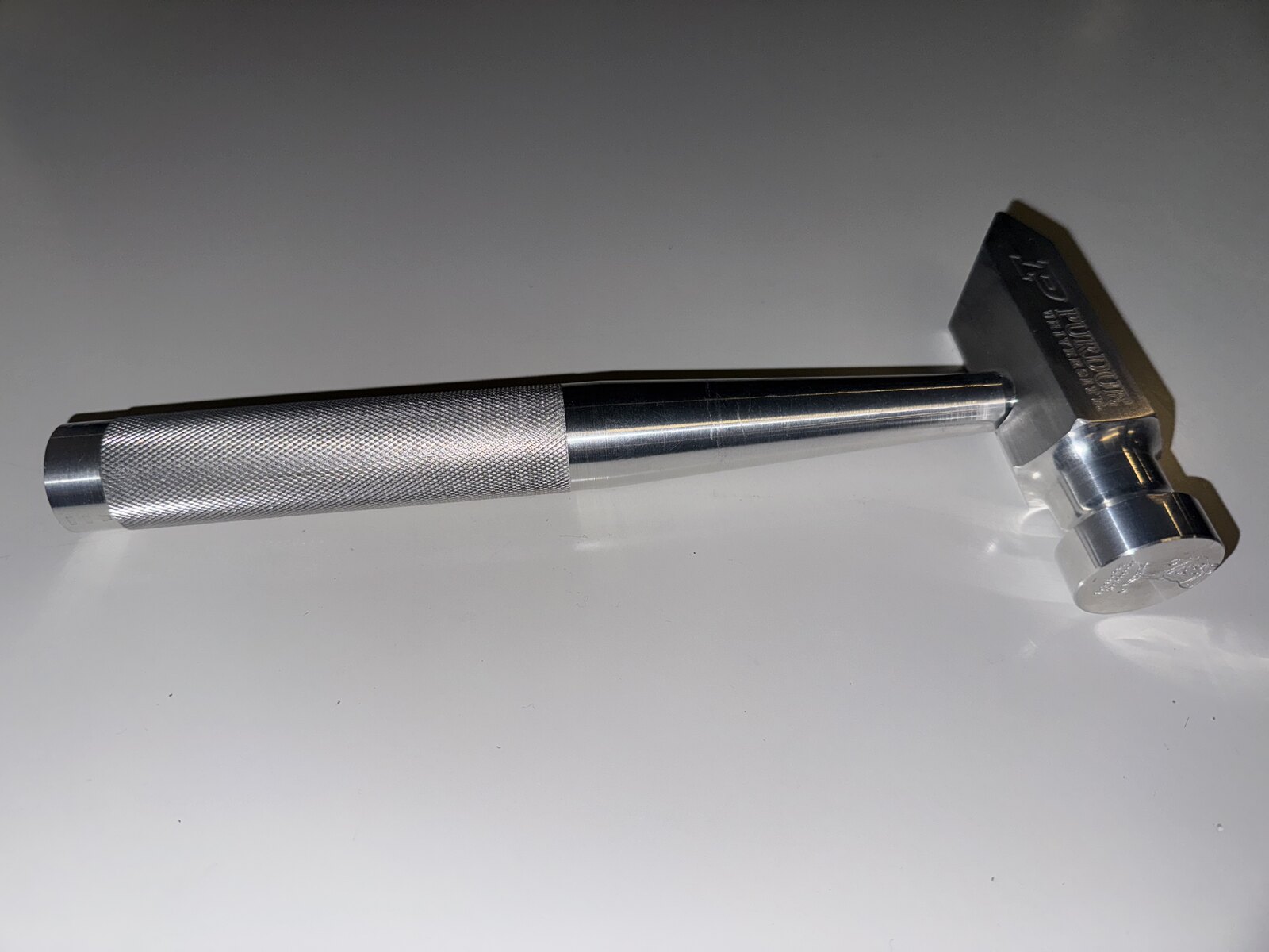
- Incorporate the course hammer we made earlier in the semester into a desk organizer, and display it.
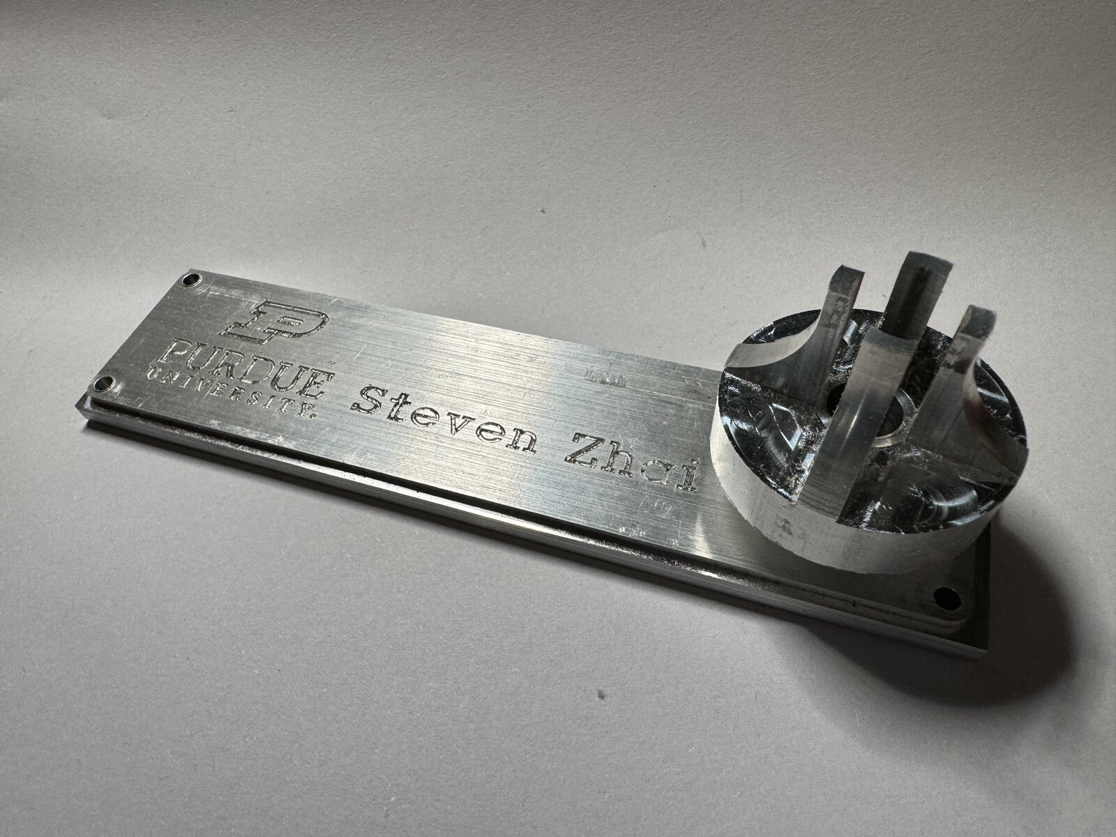
- Reuse other parts we made earlier in the semester (metal nameplate, fountain accent, electronic clock module).
- Store stationery somewhere easily accessible.
- Build it with what the Purdue ME shops and maker spaces have, mostly laser cutters, hand tools, basic wood-working stations, and sheet-metal forming.
- Keep the fastener count low. In a Design for Assembly class, screws are the enemy.
We landed on a dual clock-tower pen holder, styled after the Purdue Bell Tower. The hammer becomes the crossbeam. A pen basket hangs off it and swings.
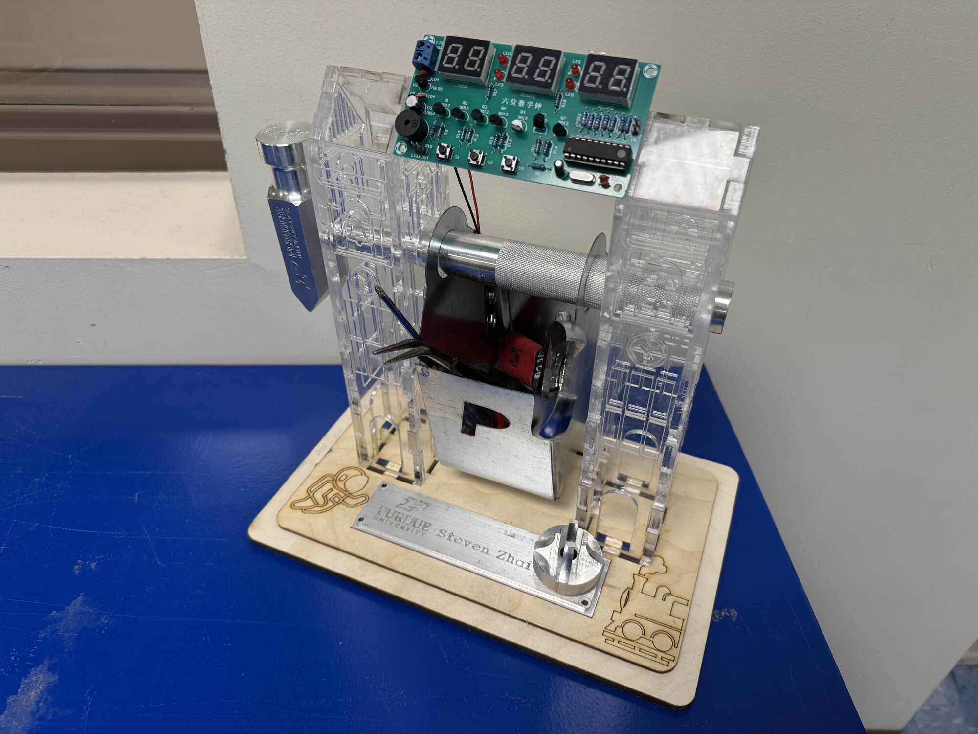 The finished prototype. Hammer runs through both towers, clock module up top, nameplate in the base.
My Role
With only two of us, most responsibilities were shared. I co-led the CAD and drawings, ran the acrylic tower cuts and glue-up, owned the bill of materials, and handled fit checks. Oliver led concept sketching, formed the swing bracket on the press brake, and prepped the plywood base.
From Function to Form
Form came last. We began by asking what the organizer had to do, then broke that into sub-functions before drawing anything.
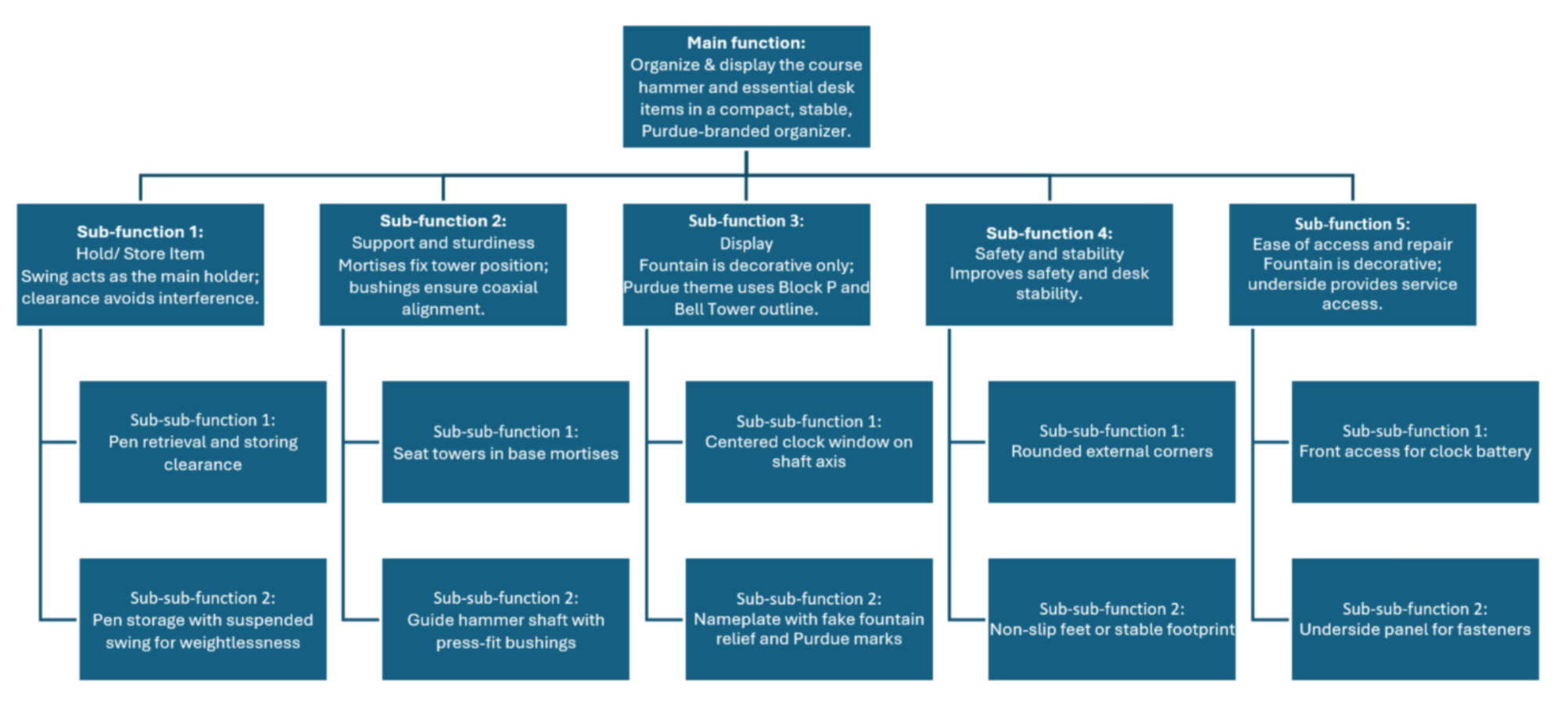 The function tree came before any geometry. Key functions were holding items, showing the clock and branding, staying stable, and allowing repair access.
That tree fed three rough architectures:
| Concept | Idea | Verdict |
|---|---|---|
| Single mast | Hammer as an inclined pole with hanging cups | Tippy |
| Low block | Hammer stored flat behind a small wall | Boring, hid the hammer |
| Twin clock towers | Two verticals, hammer as the crossbeam, swinging basket | Winner |
The weighted matrix, scoring each concept against ranked criteria, put the towers first on stability, manufacturability, part count, and how well they showed the reused parts. They also looked like a bell tower, which settled the theme.
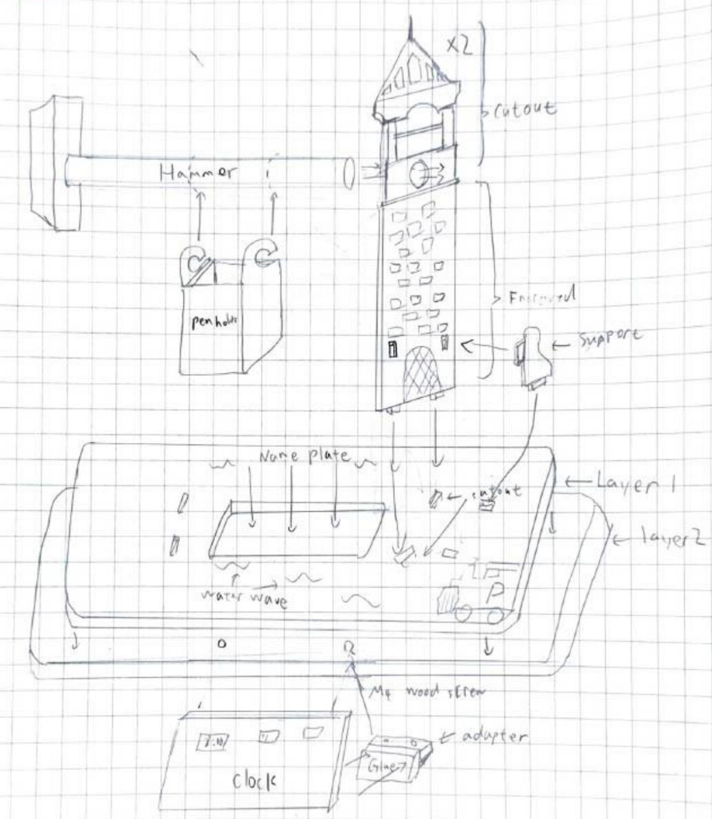 The design freeze sketch: hammer crossbeam, pen basket, layered base with nameplate and clock.
The Design
There are three kinds of custom part in the desk organizer, plus the reused hardware:
- Laminated plywood base (two layers, 1/4 in + 1/8 in) glued into one stiff block with slots and pockets cut in.
- Two acrylic towers, each four clear panels plus two roof lids, glued into a shell.
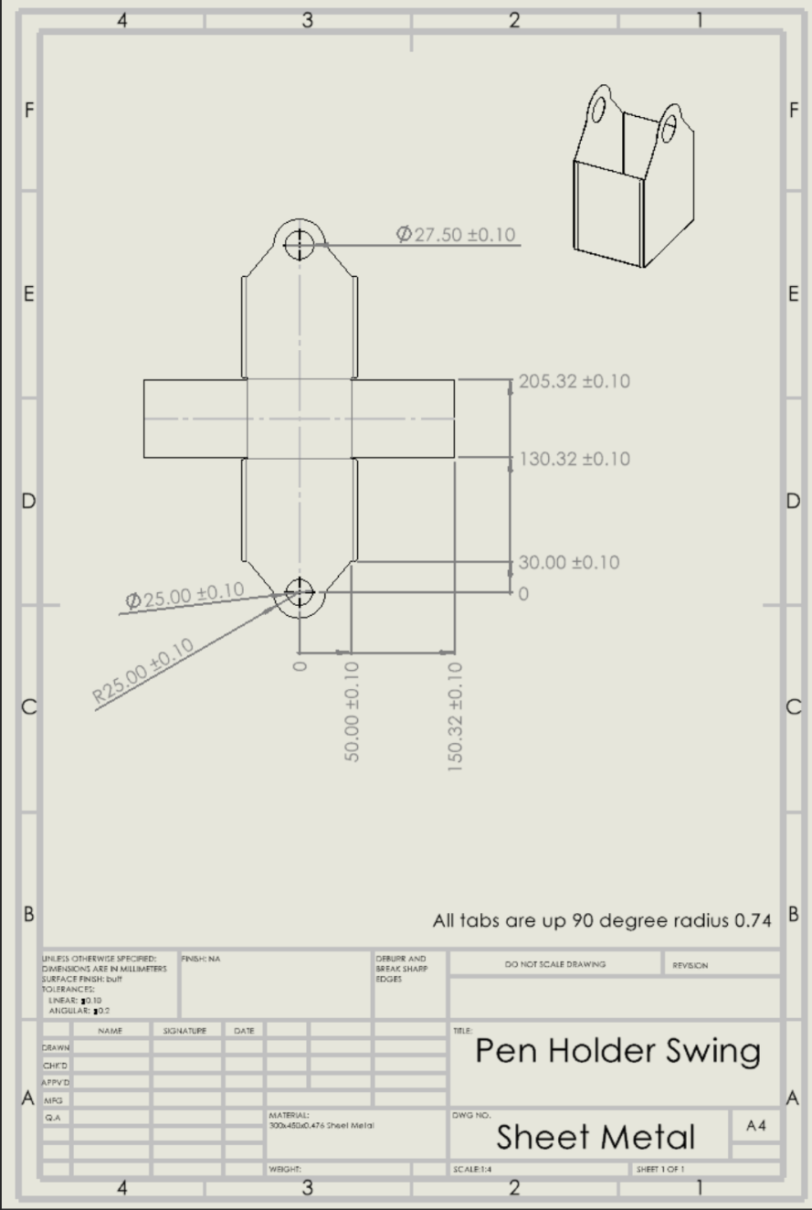
- One sheet-metal swing bracket bent into a U to cradle the pens.
- Reused nameplate, fountain, and clock press-fit into their own pockets. The hammer rod slides through the towers and turns.
That reused hardware came from earlier labs in the semester, machined on the mills and lathes so we would learn the standard shop equipment.
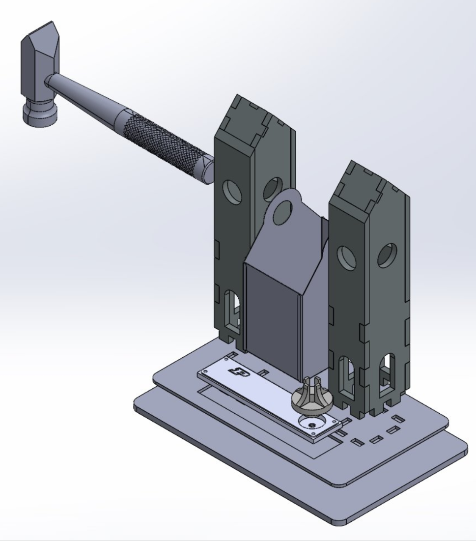
No screws, no bolts. Everything is positioned by tab-and-slot joints and held with glue.
Laser kerf is what the press-fits are designed around. The beam vaporizes roughly 0.1 to 0.2 mm as it cuts, which leaves every slot that much wider than the line you drew. Draw the slot a touch narrower than the tab and the kerf brings it back to a snug fit. A slightly tight slot pinches the tab and holds it. The DFA scorecard backed up the fastener-free design:
| Section | Score | Max |
|---|---|---|
| Overall assembly | 15 | 20 |
| Part retrieval | 6 | 10 |
| Part handling | 12 | 15 |
| Part mating | 12 | 15 |
| Total | 45 | 60 |
Every part is symmetric, every insertion is straight-line, and every pocket self-locates. Assembly is stack, align, glue.
Making It
Nearly every surface came off a laser cutter. The plan was to let the cutter do the precision work.
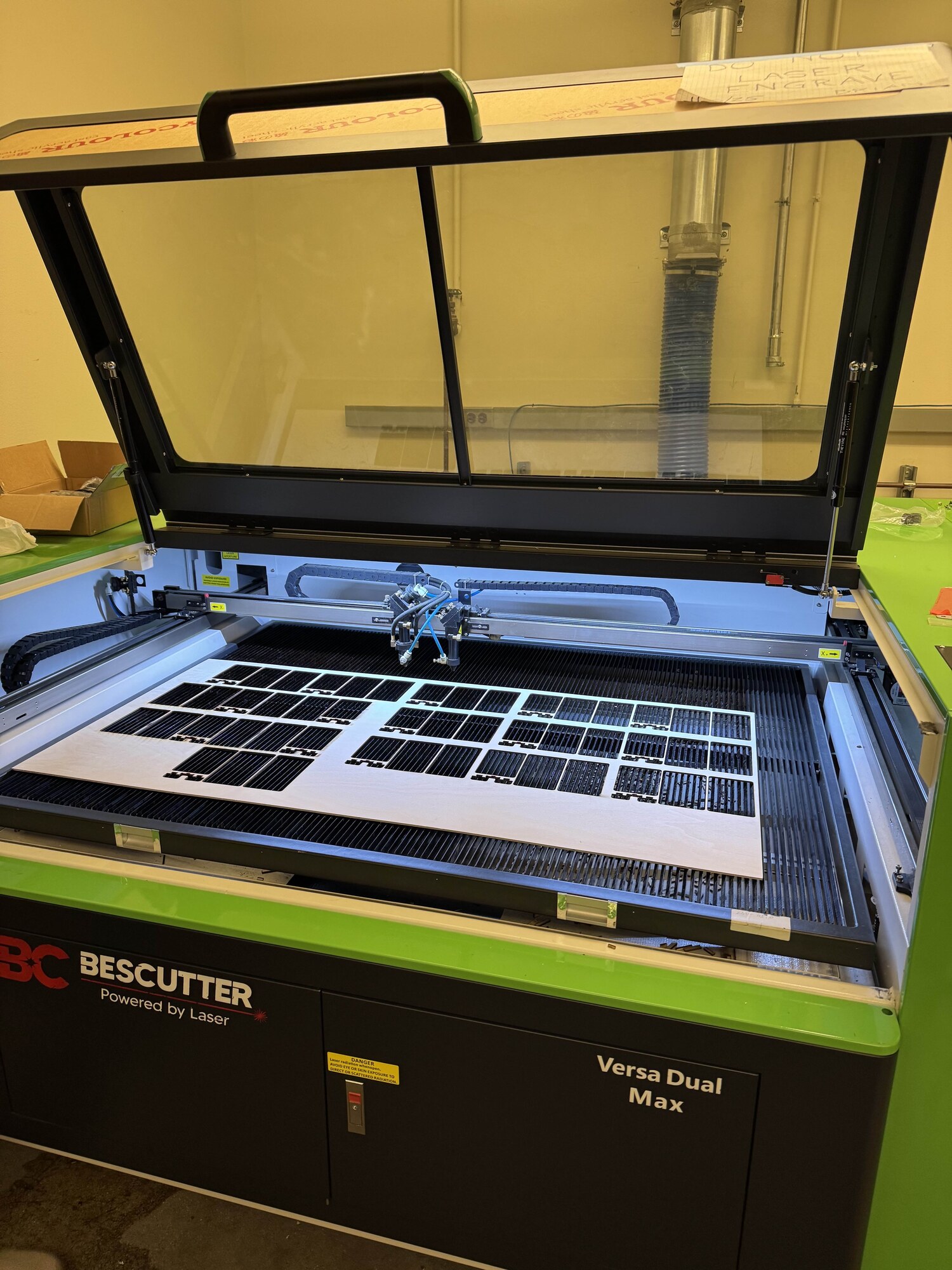
The build, part by part:
- Base. Laser-cut both plywood layers with the tower slots and the nameplate pockets, then laminate them into one stiff block.
- Towers. Cut the acrylic with the protective film left on to avoid scratches, engrave the Bell Tower detailing at low power, then glue four panels and two lids into each tower.
- Swing bracket. Laser-cut the flat pattern and bend it into a U on the press brake. The flat pattern carries a bend allowance, the extra length the metal needs to wrap around the bend. Once the legs fold up 90 degrees, the spacing matches the tower gap and the hammer rod spins free.
- Final assembly. Drop the towers into the base slots, set the swing between them, and slide the hammer rod through. Nameplate and clock press in last.
Total build time: about three hours.
- Laser cutting and stock prep: 1.0 hr
- Sheet-metal cut, deburr, and bend: 0.5 hr
- Acrylic post-processing: 1.0 hr
- Assembly and gluing: 0.5 hr
Results
- Hammer displayed prominently, center of mass sitting between the towers.
- Swing bracket holds a fistful of pens and self-centers on gravity when you let go.
- Sits flat and stable, with rounded corners so nobody stabs a hand.
- Zero fasteners. Tabs, pockets, and glue only.
The laser held tolerance well. We calipered every overall dimension plus more than 30 slot and hole positions across both base layers and the towers. Nearly all of them landed within a few tenths of a millimeter of nominal:
| Feature | Nominal | Measured |
|---|---|---|
| Base length | 275.00 mm | 274.82 mm |
| Base width | 175.00 mm | 174.65 mm |
| Tower face height | 233.00 mm | 232.81 mm |
| Tower face width | 94.00 mm | 94.07 mm |
The hammer handle passed through both towers and the bracket with no visible sag. The engraving came out clean on every acrylic face. It looked like the design file.
What I’d Change Next Time
- The hammer-rod holes ran tight. The same undersize offset that makes the press-fits grip also left the hole the rod turns in too tight. Knurling on the rod did not help either. A bit more clearance in CAD would make assembly less of a fight.
- The clock wiring needs a real cable channel. Right now it dangles off the back of the stand.
- A stain or clear coat on the plywood would hide the laser scorch and toughen it up.
- A small non-slip pad underneath would keep it from sliding on smooth desks.
The Ultimate Takeaway
What worked was starting from function, letting tab-and-slot joints do the work of screws, and trusting the laser to hold tolerance. The result came out stable, fastener-free, and accurate to a few tenths of a millimeter. It was built in less than three hours, so not bad for a conceptually gravitational over-actuated system.